@techphobic wrote:
hi all,
From UK
Hope to learn and then to help where I can
Posts: 2
Participants: 2
@techphobic wrote:
hi all,
From UK
Hope to learn and then to help where I can
Posts: 2
Participants: 2
@techphobic wrote:
Hi All,
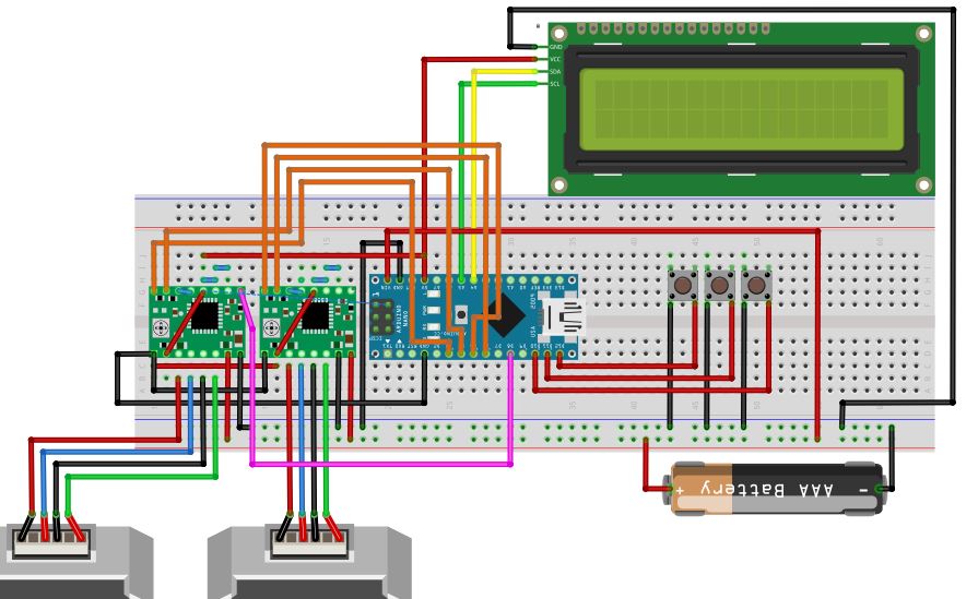
I am trying to replicate a project found on youtube https://www.youtube.com/watch?v=Ixln9wI0_uQ
It is similar to what I need but there is no clear circuit diagram.
i want to set it up on breadboard and then adjust code to my needs. Teaching myself both arduino and fritzing on something of interest to me rather than trying to absorb information from 50 odd tutorials.
From the limited visuals on the video, I have tried to duplicate it in fritzing.
I will try to upload a picture of what I have created on fritzing, please ignore the battery powering it, I intend to use 12v dc 3 amp power supply.
If anyone has the time to take a look and offer any help regarding any issues, thank you in advance.
Posts: 1
Participants: 1
Hi there
My first message here.
I am sharing an so far unfinished design for controlling our next design of covid-19 emergency ventilator, see https://tribun.cloud/index.php/s/mzqPWbDTTHnb4xj go into folder Ch(air) then Controller.
I am an experienced electronics engineer, but have used other CAD before. I chose Fritzing in order to make a nice looking and usable prototype board view to share. But… in board view it looks really messy and hard to follow!
The biggest problem are the capacitors that are supposed to be standing are displayed overlapping other components.
I think Fritzing really need standing component views of capacitors, LEDS, transistors, etc - and partly translucent. Wires semi translucent too. I do not have time to draw symbols myself - By the description it seem very complicated to do. Is there a good collection somewhere that may suit my purpose?
Any suggestion to make the board design better readable by little effort?
BTW, this is a competition me and a friend design this ventilator for: https://give-a-breath-challenge.innosabi.com/ In the link i gave you an find more on our odd ventilator - that actually do meet all needed specifications 
Best Regards
/Morgan
6 posts - 2 participants
(topic withdrawn by author, will be automatically deleted in 24 hours unless flagged)
1 post - 1 participant
I’m at work, so I can’t provide screenshots right now, but hopefully this is something that doesn’t require it.
Created a custom PCB, and then placed SMD parts on it. The parts appeared reversed, as if they were placed on the bottom side of the PCB, (with the circle indicating pin 1 at the upper right instead of the upper left) even though they were on the top side of the board according to the inspector. I don’t know if this happens with through-hole.
Unable to create TSSOP-16 parts. The default 74HC595 part does not allow me to select TSSOP-16 as the package type. So I chose a generic IC, set it to 16 pins, and then set it to TSSOP. When I do that, it sets it to TSSOP, but with 20 pins. So I chose 16 pins from the dropdown, and the part reverted to SO(w)-16. I am unable to create a TSSOP-16 part.
0.94
3 posts - 2 participants
Hi,
Paypal is not operating in Turkey at the moment and I can’t pay towards my download.
Is there and alternative way to pay or it is such that I simply can’t use Fritzing in here?
Thanks.
1 post - 1 participant
Here it is my part design that corresponds to a two channel thyristor. This module it’s also known as a AC dimmer due to it can be used apply PWM control a led strip or any 220V AC load.
Thyristor AC swith - 2 channel dimmer.fzpz (74.3 KB)
2 posts - 2 participants
Hi all. Trying to get started with Fritzing on Ubuntu machine. Installed program twice, and still generates this error for all the parts.
Any advice would be gratefully received
Davy

3 posts - 2 participants
Hi there,
first and foremost: As many posts start with the same phrasing, I’ll pitch into that:
I have virtually no knowledge when it comes to electronics.
Nevertheless, for the past few months I tried to design a robot for no specific purpose other than to fool around.
So I created a Fritzing Schematic for documentation purposes.
I would appreciate any kind of input on the circuit, it is fully functioning as I want it to, I was just wondering where I might improve. I am relatively confident I could get rid of a few wires.
I’d like to create a perforated board for this circuit and thought I might layout that with fritzing and its “auto routing” feature. I invested a few hours to get it look “as good” as it does right now. I just seem to be unable to understand a few routings - f.e. A2 + A3.
Looking forward to any advices / tips on how I might improve.
4 posts - 3 participants
At last I started to make a new PCB after a long time and have to remember how I did things in the past. Now, I stumble across a problem: when I want to move some components simultaneously and start to select them using my mouse then always the PCB outline moves.
So I first have to move the outline away from those components be able to select them.
Is there a way that can I avoid this moving of the PCB outline or deselect this?
2 posts - 2 participants
help how can i create a perforated slot for a voltmeter as component
7 posts - 4 participants
I need help. I paid for the Download, got the zip files exported but in folder. There is no fritzing.exe file to click to download application. How do i download files for Windows10
2 posts - 2 participants
Hi everybody,
I’m Sharing a part: RF69; this is a radio transmitter
RFM69.fzpz (14.5 KB)
1 post - 1 participant
Is it possible to dictate which side of the through hole gets the copper pad on a double sided board?
7 posts - 2 participants
Hi there!
I am trying to calculate the necessary trace width for certain traces on my pcb with online calculators.
From googling around I found out that fritzing/aisler produces pcbs with a copper thickness of 35 um which is one variable needed for the calculation. ( I hope the 35 um are correct).
The online calculators always calculate a trace width for internal and external traces.
I think that my traces are external but I am not sure. I am unsure because the traces on the pcbs are enclosed by the surface-finish-layer. Does this surface-finish-layer make all traces internal traces? Probably not, but I am not sure, so hopefully someone of you knows an answer, so I can be sure which calculated trace width is the correct one for me:-)
Btw: My pcb is a one-layer-pcb. So I have the electronic parts going in on the top side and all the traces are located on the bottom side. I am not using any vias or so.
Thanks, jagup
4 posts - 3 participants
Hi,
I have built my first schematic in Fritzing. Many of the connections terminate at GND.
In Breadboard view, I want to set the columns on either side of the many rows as as +V, -V and GND.
Does Fritzing understand that I can make many common connections to a breadboard column? If so, what is the neatest way to achieve this, so that components going to ground only connect to that column, and not to each other?
When I make a GND connection from a component to a column, to make that column represent GND, the component I’ve connected also connects a wire to another component which has a connection to GND. I want the components to connect to the column, but not to each other.
I hope it makes sense - thanks!
2 posts - 1 participant
I am working on a low cost potentiostat-galvanostat assembly project. In the first step I am working on the triangular ramp (triangular wave). I am using the Adafruit MCP4725 DAC in bipolar mode (page 31 of the datasheet). From the photo, you can see that it is working perfectly, generating a ramp of approximately -2.5 to +2.5 V vs GND, I thought it was great. Now I decided to include an ADS1115 ADC to measure the potential generated by the MCP4725. From the ADS1115 datasheet I know that the power must be between 2 and 5.5 V and I also know that I can measure potentials between -0.3 V vs GND and +0, 3 vs VDD. As the signal generated by MCP 4725 goes from -2.5 to +2.5 V vs GND, if I try to measure this signal I will burn ADS1115. For this reason I used the ICL7660 converter to generate -5.0 V vs GND. Then I used two voltage dividers to get -2.5 vs GND and + 2.5 vs GND to use in the ADS1115 supply, so -2.5 goes to GND and +2.5 goes to VDD. The problem is that it is not working, when I run the program to scan I2C addresses the arduino does not recognize the ADS1115 powered in this way. I must say that in reality my voltage divisors result in -2.33 and 2.37 V vs GND but it still theoretically works to feed ADS1115. I don’t know if the voltage level changes anything at the output of the SCL and SDA pins, I don’t know if it would be the case of using an MEGA arduino because it has two I2C outputs because I’m using a nano arduino. Thank you for your help.
1 post - 1 participant
Has anyone created this part or could someone please create it for me?
2 posts - 2 participants
Hello,
I am trying to track down a part number on my system. I used the search tool provided by Fritzing in the Fritzing interface but I am coming up empty.
I keep trying to put in a part number w/ the .fzpz suffix. It will not let me. The fritzing software keeps telling me I already have a part number w/ that part number.
Has anyone come across this issue before?
Seth
1 post - 1 participant
PoolWx.fzz (41.0 KB)
Hello. I made a simple Weather station and also have 2 waterproof thermos to take different water temps. I suck the data into node-red and do other things from there (openweathermap, NOAA, UV index).
I tested it via breadboard and it ran rock-solid for a week straight outdoors so I got some proto board to make it more of a prototype and reduce the size/wiring to put it into a temporary Wx box.
When I soldered up the proto-board last night I followed the .fzz file and tried to make some shortcuts (piggyback connections) and also had to change some things since I am not powering a breadboard rail anymore. The sensor would not work, and I am sure it is my wiring “shortcuts” I tried creating.
Before I dig in to solve the problem, I was hoping for some tips/critique of my layout and how I have things connected. – I might as well make it the best I can right now if I am going to re-do some wiring.
Am I wiring this for best power consumption/operation? I am using Deep.sleep and was surprised that my powerbank ran it for only a week before dying. I only take measurements every 15 min. Maybe that 280 and the temp sensors are not powering off during deep sleep?
I have 18650’s, holders and charging chips to use, but could never get the 8266 to boot via battery, so I figured I would just swap out the powerbank once in a while. I have a small solar cell I was willing to incorporate too, but the project was all working, so I wanted to take the “W” while I had it in hand. Why can’t I just add the 18650 to this setup?
1 post - 1 participant