@kenpeacez wrote:
Hi, I need help for this part YK04 RF Receiver Module as I cannot find it anywhere on the internet for Fritzing.

Posts: 1
Participants: 1
@kenpeacez wrote:
Hi, I need help for this part YK04 RF Receiver Module as I cannot find it anywhere on the internet for Fritzing.
Posts: 1
Participants: 1
@gkean13 wrote:
Sorry Everyone, I’m new here, but I have been looking around for the CD4021BE Shift Register, but don’t see it. I have also found that others have asked about it but could not find any resolution. It looks like someone created a “custom” item, but also can’t find that. It also looks like it was supposed to have been added to release, but again, I can’t find it. Sorry if I have missed something.
Thanks for your help,
Gary
Posts: 3
Participants: 2
@simoneengelbr wrote:
Hi!
Is there any way to view/display a .fzz file on a website? Would love to display it directly instead of manually exporting as an image whenever a file is changed.
Hope you can help!
- Simone
Posts: 1
Participants: 1
@gpcullip wrote:
Hi Peter
As I am getting into part creation a little more each day whilst learning a great deal, I find myself looking for at the Frizing core part variables and designations like connector#terminal, connector#pin, terminalid, svgid with the various files.
If find myself asking the same questions over and over:
- “Are the more variables and designations I should be aware of?”
- “Is there a list of all of these variables and designations somewhere?”
As your aware I’m not a software engineer by any stretch (my terminology may be a little rusty), but I have dabbled in the past with various languages so the syntax’s are familiar enough I can navigate and make sense of them.
Kind regards
Glenn
Posts: 1
Participants: 1
@Antoine1255 wrote:
Bonjour,
je souhaiterais contrôler mon moteur grâce à un bouton poussoir. Lorsque j’appuie sur le bouton, je voudrais que le moteur tourne pendant 30 seconde, et qu’il s’arrête une fois fini. Je ne vois pas où est l’erreur dans mon programme et le bouton est bien reconnu dans le moniteur série. J’utilise un bouton 2 broches mais sur le schéma c’est un 4 broches. J’utilise un Arduino Uno. Le but final serait de relier le tout à un écran LCD en I2C (la partie de l’écran avec le bouton est déjà terminée), afin de faire en sorte que lorsque j’appuie sur le bouton, le moteur tourne pendant 30 secondes et un opération se fait sur l’écran LCD.
/
Hello,
I would like to control my engine with a push button. When I press the button, I would like the engine to run for 30 seconds, and stop when finished. I don’t see where the error is in my program and the button is well recognized in the serial monitor. I use a 2 pin button but on the diagram it’s a 4 pin. I’m using an Arduino Uno. The final goal would be to connect everything to an LCD screen in I2C (the part of the screen with the button is already finished), so that when I press the button, the engine runs for 30 seconds and an operation is performed on the LCD screen.Le programme / the program :
int pin1Moteur1=12; //cmd 1 du moteur 1
int pin2Moteur1=8; // cmd 2 du moteur 1
int pinPMoteur1=11; // PMM du moteur 1
int pinBouton=7; // bouton poussoir
int EtatBouton;void setup()
{
Serial.begin(9600);
pinMode(7,INPUT); //Signale à l’Arduino que la connexion 7 doit pouvoir recevoir du courant
pinMode(12,OUTPUT); //Signale à l’Arduino que la connexion 13 doit pouvoir envoyer du courant
pinMode(8,OUTPUT); //Signale à l’Arduino que la connexion 8 doit pouvoir envoyer du courant
pinMode(11,OUTPUT); //Signale à l’Arduino que la connexion 11 doit pouvoir envoyer du courant
}void loop()
{
boolean a=digitalRead(7);// et on l’affecte à la variable “a”
Serial.println(a); // on l’affiche sur le moniteur
delay(5);if (EtatBouton == LOW);
{
digitalWrite(12,HIGH);
digitalWrite(8,LOW);
analogWrite(11,255);
delay(5000);
}if (EtatBouton == HIGH);
{
digitalWrite(12,LOW);
digitalWrite(8,LOW);
analogWrite(11,0);
delay(5000);
}
}Merci beaucoup / Thank you very much
Posts: 1
Participants: 1
@BobGreenwade wrote:
I’ve done a search, and found that this was an issue with a posted solution about 6 years ago, but that solution is no longer available (as far as I can tell). I have a board under way with a MAX4468, and this has been a major hangup.
Posts: 2
Participants: 2
@Thorsonic wrote:
I went ahead and paid (v.9.4)and spent two hours designing something that has proven to be frustrating. the cartoon like parts for stripboards is haphazard cartoonish looking parts that are frustrating to use.While the software does have amazing features and useful in some regards, I find, IMO parts should be more closely resembling the PCB layout (true Top Down). The cartoon angled parts interfere with the view of other things on the board and are inflexible, like standing up resistors not possible. Sure, I could change spacing (PCB view) but no-good for the cartoon part… cant hack in to it to fix as takes time away from my getting this proto up and running… I had high hopes but I will not be using this for breadboard stripboard layout it seems. The cartoonish /angled view not helpful. … PCB layout looks okay, not what I bought it for, but will use for this…
if /when a new version coming out with non-cartoon parts that are true top down view just like (PCB View) what it is in real word for perfboard creation, I will be back to try again - Good luck thanks for listening.
Posts: 2
Participants: 2
@provejac wrote:
I don’t know why APA102-2020 we are currently using consumes a lot of power and has a high defect rate, does anybody have same problem? I think the manufacturer changed the IC, or find other factory to produce APA102-2020 LEDs, so cause many mistakes.
I found NS107S-2020 in google, similar to APA102-2020, maybe clone, but really good performance, perhaps it is the old APA102-2020 IC, anyway it is really good, i used it for my new product, every piece include 80pcs NS107S-2020 LEDs,
Posts: 1
Participants: 1
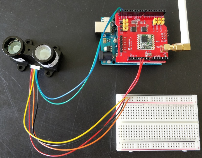
@simoneengelbr wrote:
Hi!
I’m using this part: LIDARLite-Fritzing-Part.fzpz (10.7 KB) , but I believe the wires/pins have been added in a mirrored/opposite order, possibly due to this SparkFun view drawn from below:
.
The actual order of the pins can be seen in this photo:
I don’t think it is very user-friendly to display one of the sensors in my system upside down. Does anyone have experience changing the names/connections on a part? I only need the breadboard view, so I guess i could try and edit the text on that file. What else should I change in order to correct the part properly?
Best,
Simone
Posts: 2
Participants: 2
@gpcullip wrote:
Hi Peter
I think this series of CD4060B IC’s is ready to submit.
Please could you take a final look at these…
14 STAGE BINARY COUNTER OBLONG.fzpz (9.1 KB)
14 STAGE BINARY COUNTER SOIC.fzpz (7.4 KB)
14 STAGE BINARY COUNTER STD.fzpz (8.5 KB)
14 STAGE BINARY COUNTER TSSOP.fzpz (7.7 KB)Hopefully I have managed to create the “family” grouping correctly. With the SMD parts, I have changed the “type” attribute from “male” to “pad” for the connectors within the .fzp files.
Kind Regards
Glenn
Posts: 4
Participants: 2
@Francolotto wrote:
Ciao a tutti sto lavorando a un piccolo progetto per la gestione di alcuni sensori, avrei bisogno di un progettino utilizzando il famoso pic 12f509 per far funzionare 5 led in sequenza e poter regolare la velocità. Si può fare il firmware per questo integrato? Ovviamente se devo pagare qualcosa non ci sono problemi. Ringrazio tantissimo.
Posts: 2
Participants: 2
@Blue wrote:
Here more 30 parts, New & some Improved parts…
71. SCR (TO-220).fzpz (8.6 KB)
72. SCR (SOT-23).fzpz (6.8 KB)
73. Shunt 431 (SOT-23).fzpz (5.3 KB)
74. Dual Op-Amp (358,393).fzpz (10.9 KB)
75. Dual Op-Amp SOP8.fzpz (10.9 KB)
76. Single Op-Amp SOP8 (3140,741).fzpz (10.8 KB)
77. AC Supply (sub).fzpz (9.6 KB)
78. AC Supply 400.fzpz (8.0 KB)
79. AC Supply 300.fzpz (8.0 KB)
80. AC Supply 200.fzpz (8.2 KB)81. Resistor 5W (ceramic).fzpz (4.6 KB)
82. Resistor 5W (wirewound).fzpz (5.7 KB)
83. PCB Fuse with cap (new pin).fzpz (2.5 KB)
84. Diode (M7).fzpz (6.0 KB)
85. Bridge Rectifier (SO4,MDI,MDF) .fzpz (8.8 KB)
86. Silk - capacitor_5x6.fzpz (2.3 KB)
87. Silk - capacitor_8x12.fzpz (2.4 KB)
88. Silk - capacitor_8x16.fzpz (2.4 KB)
89. Silk - capacitor_10x13.fzpz (2.4 KB)
90. Silk - capacitor_12x21.fzpz (2.6 KB)91. Silk - capacitor_18x34.fzpz (3.2 KB)
92. Capacitor 3300uF (18mm).fzpz (2.0 KB)
93. USB-A Male (New Terminal) .fzpz (7.5 KB)
94. USB-A Female (Stand 90) .fzpz (7.1 KB)
96. USB-A Male (New SMD) .fzpz (7.2 KB)
97. NPN (TO-3P) (BCE).fzpz (4.2 KB)
98. Diode - DO41_400mil.fzpz (1.5 KB)
99. Diode - DO201AD_600mil.fzpz (1.5 KB)
100. Diode - DO201AD_700mil.fzpz (1.5 KB)Lots of them are provided by fritzing with wrong pitch (or maybe different variant), that I had to edit… Hope that will help someone…
If there is any error, problem, mistake… Please Let Me Know…Batch File of 100 parts: (Latest & Updated)
my_parts (1-100).fzbz (775.1 KB)
Posts: 1
Participants: 1
@brulics wrote:
Hi.
I just created a project (I’m rookie) with raspberry zero w and YL-83 rain sensor.
I always have same error message on DRC results:Connector POS on Part YL-83 Rain Sensor - Control Board 'YL-83 - Control Board1' should have both copper top and bottom layers, but the svg only specifies one layer. Connector NEG on Part YL-83 Rain Sensor - Control Board 'YL-83 - Control Board1' should have both copper top and bottom layers, but the svg only specifies one layer.Here is my project https://fritzing.org/projects/raspeberry-zero-yl-83-rain-sensor
Do you have any idea about this error?. I’m lost about how to fix it.
Thanks.
Posts: 4
Participants: 2
@axl wrote:
I’m looking for raspberry pi 4 B for fritzing. I need the raspberry for my project
Posts: 1
Participants: 1
@furkankilic wrote:
Hi Friends!
Im new at using Fritzing. I need STM32407VG Fritzing folder to use it. I serch on google but I could not find any ready folder. Can anyone share it with me? Thank you!
Posts: 1
Participants: 1
@GreyHobbyist wrote:
i’m confused. i donated and purchased the latest version today. Great tool. i spent all day creating three custom parts. They show up in my parts bin. i create three circuit files, versions of each other. i decided to start over. i deleted the files. I discovered creating a new circuit that my parts bin is now empty. Aaaaaaarrrrrggggghhhhh!!! Uhhh, the bin is temporary? Should I have known to somehow squirrel it away for future use? I had to stop development until I figger out how to make them all over again and remember them. Bad taste in my mouth.
Posts: 2
Participants: 2
@axl wrote:
(topic withdrawn by author, will be automatically deleted in 24 hours unless flagged)
Posts: 1
Participants: 1
@gpcullip wrote:
Hi Peter
Please could you advise me on the dilemma of my schematic not displaying on the Fritzing Schematic view correctly (on the left), yet when editing in Parts Editor the schematic displays correctly (as drawn in Inkscape)? Is there an old file Fritzing is calling up somewhere?
Also Fritzing has now started reporting “unable to load part” for all my parts, I had to manually edit the “my_parts.fzb” to get the part to be visible and to work properly… Wierd?
Kind regards
Glenn
Posts: 14
Participants: 2
@ernie14MHC wrote:
Hi All,
I am very new to Fritzing (like today). I want to uses it to document an exist stripboard for future reference. On the physical board when I want cut the track I use a tool that splits the track at one of the existing holes. When it comes to designing the board in Fritzing I can only find a method to cut the track between two holes.
Is there a method to cut the track at a hole?
Thanks
Ernie
Posts: 2
Participants: 2