December 7, 2016, 1:38 pm
@rricardo wrote:
Hi,
unfortunately i'm facing an error which totally breaks usability for me.
When inserting a via1-part into the pcb sketch and trying to set up his placement whenever i filled one of the location textboxes fritzing seems to alter my dimensions. I've got a PCB of 400x90mm, and i was trying to insert row of 5 pcs of vias in a row to make a custom header (standard 2.54 spacing), i was trying to place the first via at x= 28.1mm y=14.75mm
When i enter those dimensions my 28.1mm are being altered to 28.077mm and my 14.75mm to 14.739.. I tried disabling the snap to grid feature, thought it might be a problem with the imperial measurements in the grid, switched to mm in the grid, but nothing changes. There seems to be an internal bug that prevents me from placing whatever elements where i actually want/need them. This wouldn't be a big problem if i would be able to not care about relative measurements between seperate rows of via's, but i need to mount some stuff at those exact locations, thus need the placement to work. Propably just a minor, well hidden though, bug.
That aside the whole component creating/altering thing has to change to make it actually usable, but i'm sure you've heard that 1-2 times already.
I'd appreciate help of any kind, i really like the look&feel of fritzing and want to use it, but for now i can't.
Thanks!
Posts: 6
Participants: 3
Read full topic
↧
December 7, 2016, 6:41 pm
↧
↧
December 8, 2016, 1:11 pm
@matteman69 wrote:
Hello! i have downloaded Fritzing but it says api-ms-win-crt-runtime-i1-1-0.dll is missing?
Posts: 2
Participants: 2
Read full topic
↧
December 8, 2016, 1:43 pm
@loops wrote:
Hi everyone !
I've build a PCB with a HLK-PM1 part. I've the latest version of Fritzing : 0.9.3
I can't put the HLK-PM1 on the PCB, the holes are too small :(. The distance is correct, but the holes too small ... The diameter of the pin is 0.8 mm and in the PCB i've something like 0.5 mm
I've tried to modify the HLK-PM1 part but without success !!!
Somebody can help me ???
Thanks a lot !
JC
Posts: 3
Participants: 2
Read full topic
↧
December 8, 2016, 2:08 pm
@lurchsum69 wrote:
In this screen grab you can see most of my leads connected to all of my components without issue except the red box in the lower right. That red box is a A4988 stepper driver which I got from here.
http://fritzing.org/projects/a4988-single-stepper-test/
Why are the leads for that driver not going to each individual pin like my other components? Is it just a glitch in the part that someone made?
Thanks
Posts: 5
Participants: 3
Read full topic
↧
↧
December 8, 2016, 10:28 pm
@Old_Grey wrote:
Steps I took that resulted in the problem:
Top 2 pins have lump when bendpoint is horizontal with pin, bottom 2 don't but the bendpoint isn't horizontal with pin.
If you add a bendpoint very close to the centre of a part's pin that is joined with a 45º trace that is thicker than std(24mil), the trace kicksout a protruding lump.
Add 2 resistors.
Join with a trace that is angled approx 45º
Made trace thicker than 24mil.
Click on trace and slide a bendpoint close to the resistor leg pin so that's it's horizontal to the pin but one grid-snap to the side.
I saved the sketch, closed it and restarted, but it's still there.
What I expected should have happened instead:
No lump kickout on trace.
...
My version of Fritzing and my operating system:
Win7 64 SP1
FZ V0.9.3
...
Please also attach any files that help explaining this problem
Posts: 1
Participants: 1
Read full topic
↧
December 9, 2016, 9:34 pm
@ayuesh wrote:
hi, i have a raspberry pi 2 model b and I want to install fritzing on it.
Posts: 1
Participants: 1
Read full topic
↧
December 9, 2016, 11:02 pm
@flenser wrote:
This is a generic TO-92 transistor that has an image of the transistor inserted vertically for the Breadboard view.
* 1. The part only has the TO-92 package. It does not have the TO-220 or SOT-23 packages that are included in the core part.
* 2. The part has NPN and PNP transistors with CBE, EBC and ECB pinouts for both types.
* 3. The part is created in the breadboard, schematic and pcb views.
* 4. The part is tested in the breadboard, schematic and pcb views.
![]()
I build my breadboard circuits with the TO-92 transistors inserted vertically, I don't bend them over flat on the board like the core Fritzing breadboard parts. This makes the Breadboard view of my circuits less WYSISYG than I'd like using the core parts.
Standard Transistor (V) - TO92 [THT] - v1.0.fzbz (23.1 KB)
Posts: 1
Participants: 1
Read full topic
↧
December 13, 2016, 8:18 am
@StickyNote wrote:
A small problem for me, but perhaps a big opportunity for Fritzing in the ever-growing SMT/SMD world—connectable PCB pads. I often have SMD parts for which no Fritzing part is currently available, but I could create one on-the-fly with the sizeable pads in PCB view, except they have no connections and do not show in the schematic view. If the pads could be circuit-connectable, then any part or device footprint could be created as-needed, without every user having to learn to modify existing parts or create new ones. With dozens of new or unique SMD footprints coming out weekly, a solution is necessary to allow Fritzing to be useful and flexible with that growth.
I am currently having to add a test point on-top of pads to make them appear in the schematic (e.g., antenna connection), but that's clumsy and messy. Is there a simple option already available, or can schematic-connectable versions of the PCB pads be developed?
Posts: 2
Participants: 2
Read full topic
↧
↧
December 13, 2016, 3:52 pm
@SunRioy wrote:
Hi, I am a beginner for fritzing, May I know where can I find the part DC power jack like the picture that I attached? Because I have been look for several website, but I can't find the part.
![]()
Posts: 4
Participants: 3
Read full topic
↧
December 13, 2016, 4:29 pm
@Old_Grey wrote:
I made a svg and loaded it into a PCB with Silkscreen Image, and it ends up an empty rectangle.
Any ideas how to fix it.
Change extension from .fzz to .svg to get image.
Speeduino logo8sm.fzz (9.5 KB)
Posts: 5
Participants: 2
Read full topic
↧
December 13, 2016, 10:27 pm
@eshore wrote:
In the PCB view, I would like to create a Jumper, so I can solder external wires and therefore create one sided PCBs that I mill myself.
Fritzing's instructions (here) say to "right-click a Rat's nest wire and choose "Create Jumper from Selected Wire(s)". The problem I'm encountering is that when I right click on the rat's nest wire, no such option to "create jumper" actually is offered to me.
Frizzing also says you can "just right-click on the trace and choose "Create Jumper from Selected Wire(s)", but once again when I do that this option is not offered.
Does anyone have any suggestions? I'm using 0.9.3 on a Mac 10.10.5. Thank you.
Posts: 2
Participants: 2
Read full topic
↧
December 14, 2016, 1:40 pm
@blweaver wrote:
I am new to Fritzing and to the Mac. I get this message when I start Fritzing on my Mac.
Where should the parts folders be?
Posts: 4
Participants: 2
Read full topic
↧
↧
December 15, 2016, 8:32 am
@Old_Grey wrote:
I Edit/Save as new part, a Schottky.
Then I Edit/META the new part and add voltage and power boxes in Properties, but leave them empty so you can add what you like in Inspector.
Back in FZ I pull the part in and the extra properties I added are in Insp, but they are not the white enter-able boxes but grey nothing.
Any ideas?
Posts: 2
Participants: 1
Read full topic
↧
December 15, 2016, 1:21 pm
@THX1138 wrote:
I have a cheap bad torch (flashlight) and I want to improve it's performance by increasing the current. It uses two white 5 mm LEDs and two AAA batteries to drive them. At 2.7 V, the current is just over 2 mA which is surely ~1 mA per LED! At 3.0 V this rises to 7 mA total or 3.5 mA per LED. I figure most cheap white LEDs are rated to take 20 mA which would make for 40 mA total. There is some IC called QX5252 which is some kind of joule thief whose current output is determined by the inductor attached externally. I was hoping could corroborate my interpretation of the datasheet before I order the parts.
The LEDs need 4.1 V to get 40 mA of current to them. That's 164 mW. I'm providing 2.4 V (dropping to ~1.6 V) .
Inductor needed at full charge = 2 x 2.4 V x 10E-6 / 0.164 W = 29 uH. Is that calculation correct?
Also, I think the energy is delivered in pulses but the datasheet is pretty rubbish and doesn't give any indication on the width of the pulses so I don't know what effect a capaitor would have for smoothing the pulses out.
Posts: 1
Participants: 1
Read full topic
↧
December 15, 2016, 6:16 pm
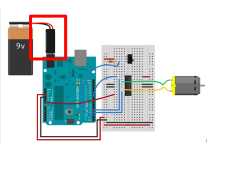
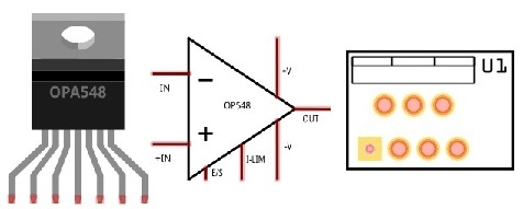
@jerburi wrote:
Hi everybody!
![]()
As I was running into the need of using a high voltage, high current amplifier for a temperature controller, I thought it would be nice to make the circuit in fritzing :-). As I didn't found any part remotely related to this, I made the little extra effort to make the part I'm using: OPA548 from Texas Instruments.
I made the breadboard, schematic and PCB version of the part. Go for it!
OPA548.fzpz (15.7 KB)
Posts: 3
Participants: 2
Read full topic
↧
December 16, 2016, 2:47 am
↧
↧
December 16, 2016, 3:15 am
@jerburi wrote:
A simple heating pad (taken from a rectangular model made with silicon), used to transform electric power into heat. The next file contains the breadboard, schematic and PCB models:
Heating_Pad.fzpz (88.3 KB)
Posts: 1
Participants: 1
Read full topic
↧
December 16, 2016, 8:50 am
@GregNelson wrote:
Brand new to Fritzing and it looks like a great tool so far. I was a little surprised that I could not find any of the Capital Advanced "surfboard" parts in the system as they're great building blocks for breadboarding. Am I just bad at searching, or are they really not out there?
For example, I'm looking for the 33006CA board as a way to mount an SOT-363 FET to adapt it for use with a breadboard assembly.
Thanks,
Greg
Posts: 1
Participants: 1
Read full topic
↧
December 16, 2016, 9:55 am
@neemeh1 wrote:
I want to know how can i send a int values from the transmitter to the receiver from RF 433MHz Transmitter/Receiver ?I'm reading values from a sensor and i want to transmitted to the receiver ?
Posts: 1
Participants: 1
Read full topic
↧