Quantcast
Channel: fritzing forum - Latest topics
Viewing all 5657 articles
Browse latest View live

Fritzing will not open

$
0
0

@wodonnell wrote:

When attempting to open Fritzing the splash screen shows then Fritzing shuts down. No messages are displayed.

Steps I took that resulted in the problem:

Double-clicked "Fritzing.exe"
...

What I expected should have happened instead:

Program should have opened.
...

My version of Fritzing and my operating system:

0.9.3b WIndows 7
...

Please also attach any files that help explaining this problem

Posts: 4

Participants: 3

Read full topic


Fritzing Part Creation Video Tutorial Series

$
0
0

@Old_Grey wrote:

I'm going to do a series of part creation videos.

Open to fullscreen and select 1080p HD in the gear symbol, bottom left corner of the Youtube window, for max clarity.

Fritzing Part Creation - Chapter1 - New Part Editor

Posts: 1

Participants: 1

Read full topic

How do I add XS3868 Bluetooth module in Fritzing Library

$
0
0

@utkarshnaveen wrote:

I'm very new to fritzing and I need help in parts creation. the part that i want to create is Bluetooth Module XS386. Please help me in this.. I'm attaching the EagleCad Schematic for this just for reference. Please help me in this.

The Board :http://www.instructables.com/ORIG/FG0/FRGD/I4PHX5J0/FG0FRGDI4PHX5J0.brd
The Schematic:http://www.instructables.com/ORIG/FUP/JZA4/I4PHX5KC/FUPJZA4I4PHX5KC.sch

Both of these are supported in EagleCad!

Posts: 1

Participants: 1

Read full topic

Ratsnest lines where they *shouldn't* be and in places that's clearly connected

$
0
0

@grpace wrote:

I've been trying to sort this out for 3 days, now, but to no avail.

I'm getting a ratnest line from 1 leg of a trimmer/potentiometer to the wiper (going through the potentiometer). This is on breadboard, schematic and pcb views.

Getting ratsnest lines between the pins of a 2-pin female header and through the middle of a capacitor on both schematic and pcb views.

Screen shots:

Could someone please explain what's happening here ??

Entire sketch:
LM384.Basic.fzz (80.0 KB)

Posts: 4

Participants: 2

Read full topic

Custom part working fine in all 3 views, but part is invisible when schematic is exported to SVG

$
0
0

@grpace wrote:

I'm sure there's some property in the part's schematic svg file that I'm missing. Anyone know what could cause this ?

Posts: 6

Participants: 2

Read full topic

Ground Fill - Still need traces?

$
0
0

@tcox8 wrote:

I am attempting to use the Ground Fill. I have seeded my ground connections. My question is.. once I have seeded them and applied the ground fill can I remove the traces that connect my grounded pins? If I attempt to do this the dotted wire line reappears as if there is no connection among all of the ground connections.

Posts: 4

Participants: 2

Read full topic

STEMTera Breadboard

$
0
0

@jpl wrote:

Hi,

I would like to share this part with the Fritzing community. This is a hybrid breadboard that has built in Arduino Uno R3 and ATmega32U2.

This is my first time creating a part for Fritzing and hopefully someone can help check if I have done the right thing.

Since this is a breadboard, it has no PCB view and I did the part mostly using a text editor because each time I added a pin in Fritzing Editor, the editor will refresh back to the top, so with 634 pins, I have no way to complete it using the Fritzing Editor.

STEMTera Breadboard.fzpz (172.8 KB)

Posts: 1

Participants: 1

Read full topic

Code for sk9822 fast led

$
0
0

@PhilXu007 wrote:

Hi
I have get a type of fast led,
is a type of 4 wire integrated digital rgb led with one data cable and one independent clock,
which make it faster signal,good for the big projects with large data transfer ,
and they claim it can share the same controller system as the apa102,
I am not sure about this,
so could I use the same code as apa102,
or anyone have new code for the sk9822
thx

Posts: 2

Participants: 2

Read full topic


I want to include some latching DTDP relays... but oh dear

$
0
0

@Barny18 wrote:

Hi
I am exploring the possibility of producing some PCBs with each board having some IO a 74HC595 shift register connecting to a ULN2803A from which each pair of outputs connecting separately to one of 4 latching DTDP relays.
I have run into a bit of a problem in that I can only find single pole/throw non latching relays in the component lists. Am I missing something, is it really this hard to get this kind of relay into my project?

I have done some searches and found similar questions but not much in the way of solutions, one person produced a useful DTDP (non-latching) relay https://github.com/Eunanibus/Fritzing-Parts that I might be able to modify, but how to get their design into my Fritzing project?

Regards.

Posts: 7

Participants: 2

Read full topic

UNO spolu s WiFi

$
0
0

@Isayash wrote:

Ahoj,
před několika měsíci byla uvedena deska UNO s WiFi Arduino-UNO-WiFi na základní desce, ale není dostupná v součástkách. Poradíte mi jak postupovat?
Děkuji za informace, příjemný konec roku a následující rok 2017.

@@@ $$$ ### === ---

Hello,
a few months ago we were presented with a plaque UNO WiFi [Arduino-UNO-WiFi] motherboard, but is not available in parts. You advise me how to proceed?
Thanks for the information, a pleasant end of the year and the following year 2017.

Posts: 1

Participants: 1

Read full topic

Tutorial: Create your own reusable Plug-n-Play breadboard modules

$
0
0

@grpace wrote:

Sometimes, when using components in several projects, it can be redundant to place and wire-up those components on breadboards each time. Here is a small, step-by-step tutorial on how to create your own reusable plug-n-play modules. We will be using the 555 timer as an example.

1) Start a new sketch in Fritzing.

2) In BB view, click on the full+ breadboard and change it to half+.
3) On the top menu, select File->Export->As Image->SVG. Supply a filename and export the image.

4) Bounce to PCB View.

5) From the CORE bin, scroll down to PCB view, click the icon for Silkscreen Image and drag it into the view.

6) In the Inspector, scroll down and click the Load Image button, locate the breadboard image you exported from step 3 and open it. The breadboard should be imported:

7) In the Inspector section, with the image selected, place the breadboard on silkscreen bottom. The breadboard will appear flipped, but that's OK.

8) On the top menu, select View->Set Grid Size and set the grid size to 0.01mm. This is important, as that resolution will allow you to accurately place headers over the breadboard image.

9) From the CORE bin, scroll down to Connection, click on Generic Female Header 2-pin, and drag it over the breadboard image, change it to a male header, and rotate it 90 degrees.

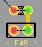
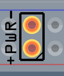
10) Zoom in close and carefully move the header over the power rails of the breadboard image:

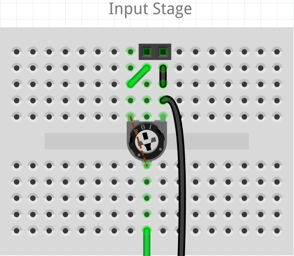
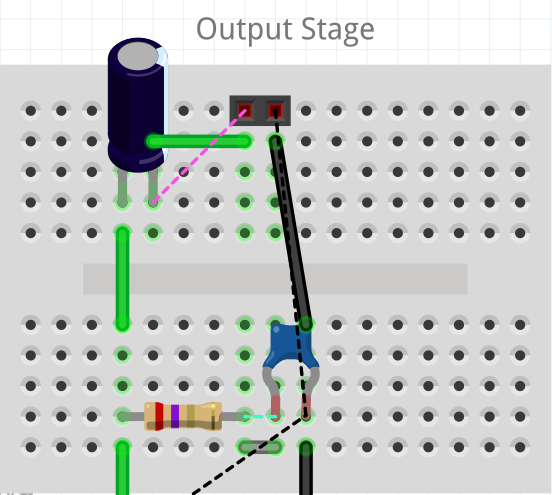
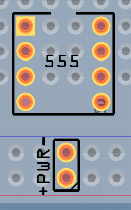
11) Add and any additional components and arrange them over the breadboard. Don't worry about them not lining up with the breadboard holes. The important thing to keep in mind here is that you'll need to reserve some breadboard holes for interfacing with your PCB:

12) Move and resize your "virtual PCB" over the breadboard image. Important here is you leave your PCB off the breadboard some so it can be selected instead of the underlying breadboard image. Set the width and the height separately.
Setting the width:

Setting the height:

Now move your PCB into place over the breadboard image.

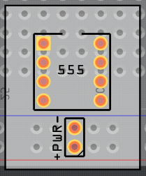
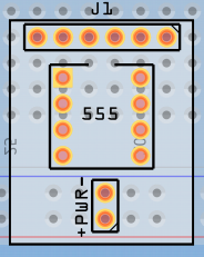
13) Add other generic headers, set them for the number of pins you'll need and carefully place them over the breadboard image:

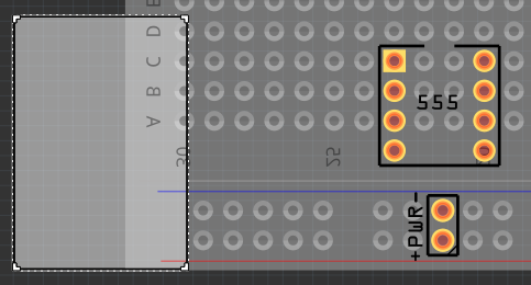
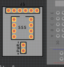
14) Left-click the mouse, hold down the button and mouse-box around your PCB to select it. This will select the breadboard image as well, so hold down the CTRL key and click the breadboard image to de-select it. Then, with the arrow keys, move your PCB from over the breadboard image:

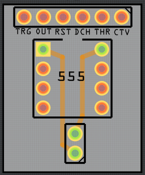
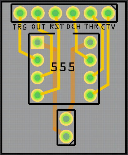
15) Using the silkscreen text tool, label the interface headers and route route your traces. I've found that the labels work better when the text height is set to 1.3mm:

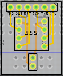
16) Mouse-box around your PCB to select it and all components, and, using the arrow keys, move it back over the breadboard image to check for accuracy:

If all is OK, you can now delete the breadboard image. Your PCB is now ready to export for etching:

Happy Module Making !!

Posts: 1

Participants: 1

Read full topic

Action only happens on last of of multiple selected iterms

$
0
0

@RichardGrace42 wrote:

This was observed for sure in Breadboard view. Pretty sure it's happening in other views also.

Steps I took that resulted in the problem:

  1. Place two parts (Rectifier diodes) in the view (specifically observed in breadboard view).
  2. Click one part.
  3. CTRL + CLICK the others in the test group.
  4. Right-Click on the view area and select action (e.g. lock part)
  5. Repeat 1-3, then click locked on the Inspector.
    ...

What I actually observed:

Only one part is acted on (seems to be the last added to the selection group).

What I expected should have happened instead:

All parts acted on. Just Like if the Menu -> Part -> Lock Part after making selection ( this even works after trying steps 1-5).
...

My version of Fritzing and my operating system:

Version 0.9.3 (b5c895d327c44a3114e5fcc9d8260daf0cbb528
Asus M5A97
* 16 GB memory
* 6 core AMD 3GHZ
* Dual Nvidia Geforce 740 GT 2GB
* (4) 27" monitors (yeah baby !)
...

Please also attach any files that help explaining this problemtest-file.fzz (1.5 KB)

Posts: 1

Participants: 1

Read full topic

Fritzing Edit acting weird

$
0
0

@Old_Grey wrote:

Can anybody work out why if you right-click/Edit this part in MINE bin there is NO error, but if you add it to the PCB view and right-click/Edit the part it gives a separate copper error. The only thing I changed was the PCB svg, and if I take that same PCB svg to the 74HC595 IC it doesn't error. I'm thinking the svg is ok, and that maybe it's in the .fzp file.

DIP - 16 pins.fzpz (6.8 KB)

Posts: 9

Participants: 3

Read full topic

AD623 SOIC8 / Low Cost Instrumentation Amplifier

$
0
0

@ccadic wrote:

name and manufacturer of the part: AD623-SOIC8 / ANALOG DEVICES
Views: (breadboard / schematic / pcb)

Single Supply, Rail-to-Rail, Low Cost Instrumentation Amplifier

https://github.com/ccadic/AD623-SIOC8

Summary

AD623-SOIC8 / ANALOG DEVICES
Easy to Use
Higher Performance than Discrete Design
Single and Dual Supply Operation
Rail-to-Rail Output Swing
Input Voltage Range Extends 150 mV Below Ground
(Single Supply)
Low Power, 575 mA Max Supply Current
Gain Set with One External Resistor
Gain Range 1 (No Resistor) to 1,000
HIGH ACCURACY DC PERFORMANCE
0.1% Gain Accuracy (G = 1)
0.35% Gain Accuracy (G > 1)
25 ppm Gain Drift (G = 1)
200 mV Max Input Offset Voltage (AD623A)
2 mV/8C Max Input Offset Drift (AD623A)
100 mV Max Input Offset Voltage (AD623B)
1 mV/8C Max Input Offset Drift (AD623B)
25 nA Max Input Bias Current
NOISE
35 nV/√Hz RTI Noise @ 1 kHz (G = 1)
EXCELLENT AC SPECIFICATIONS
90 dB Min CMRR (G = 10); 84 dB Min CMRR (G = 5)
(@ 60 Hz, 1K Source Imbalance)
800 kHz Bandwidth (G = 1)
20 ms Settling Time to 0.01% (G = 10)
APPLICATIONS
Low Power Medical Instrumentation
Transducer Interface
Thermocouple Amplifier
Industrial Process Controls
Difference Amplifier
Low Power Data Acquisition

Posts: 1

Participants: 1

Read full topic

Poor state of part SVGs

$
0
0

@sgparry0407 wrote:

Not sure where to put this - I have placed it under parts help, but other categories would be appropriate.
Basically, having spent a lot of time making / adapting Fritzing part SVGs, I have noticed that we seem to have a number of endemic problems in the parts database. This is about get a lot worse - The latest version of Inkscape is now CSS compliant, i.e. they have changed from a base resolution of 90 dpi to 96 dpi - and that could mean a lot more swearing at SVGs that don't adhere to the expected dimensions. Our problems to my knowledge fall in to the following categories:
1. SVGs created with px as base unit (thanks to illustrator)
2. Part pins and terminals not correctly aligned to breadboard or schematic grid or each other.
3. Zero sized part terminals (invisible, don't work).
4. Group type terminals (even more invisible).
5. Parts that are wildly inaccurate (mostly thanks to brd2svg being broken).
6. SVGs with ludicrously nested groups include multiple transforms (thanks Inkscape and Illustrator).
I am proposing / offering:
1. to create a set of scripts to detect / fix some of these automatically.
2. as part of (1), a set of quality control scripts - can be run by a user to check their own scripts and by el-j prior to merging in GIT. Could enforce most of the graphic standards.
3. we add metadata to indicate whether the part concerned has been checked and/or corrected.
4. Once Inkscape 0.92 is widespread Insist on 96ppi for new parts to ensure max compatibility.
I think it may be expedient to convert all existing parts to 96ppi, but that could be a mammoth task.
I cannot fix 5 - brd2svg is just huge and needs a lot of attention. To illustrate, I converted the Arduino Mega2560 ref design recently - it did not come out at 0.1 pitch or even close, components were out of line, upside down etc. This was using Adafruit's best fixed build.
Any thoughts everyone? Anybody know of other widespread issues my scripts should look for?

Posts: 6

Participants: 3

Read full topic


Large single pin part with 6.36mm diameter

$
0
0

@ead0601 wrote:

Hi,

I need to make a large single pin part with solder pads on both sides.( 0.25in = 6.35mm + 0.01mm guard)

I was able to resize a via to have a 6.36mm diameter with a 2mm ring. However, I believe the via will have a non-conductive fill in it, and I need to insert a copper piece in the hole and solder to it.
- Does the via have fill, or will it be what I want with a 6.36mm hole?

I tired resizing a single pin header, however the part grows beyond the pin bounding box, and it highlights in red.

Which is the simplest way I can create a 6.36mm single pin part, that has solder pads on both sides?
Thanks,
Ed

Posts: 4

Participants: 2

Read full topic

Ability to give wires/traces a name

$
0
0

@grpace wrote:

A nice feature would be the ability to give wires and traces a descriptive name, instead of the cryptic Wirexxxxx. The property must be there, because those labels show up in all 3 views.

Posts: 2

Participants: 2

Read full topic

I designed a PCB in Fritzing, but forgot to mirror it. How do I fix it?

$
0
0

@ailee wrote:

I designed my first PCB in Fritzing, intending to have it milled at the local hackerspace (they want Gerber files) and then assemble it with THT components.

But now all the copper is on the top side (milling two-sided PCBs is apparently way more complicated and unnecessary for such a simple circuit), and the holes are set up so that the components have to go on top, too!
The resistors and linear regulators aren't a problem, they are symmetrical, but the RJ45 connector and the MAX485 chip are not!

Is there a way to mirror the copper traces (never mind the silk screen, it's not gonna get milled anyway!)?
Fritzing doesn't seem to have the option, but it can export Gerber files.

Thanks!

This is the PCB, btw:

Posts: 2

Participants: 2

Read full topic

Help needed with a random color RGB LED program

$
0
0

@King_of_noobs wrote:

// put your setup code here, to run once:
int Pin_LED_Red = 5;
int Pin_LED_Green = 4;
int Pin_LED_Blue = 3;
void setup() {
pinMode(Pin_LED_Red, OUTPUT);
pinMode(Pin_LED_Green, OUTPUT);
pinMode(Pin_LED_Blue, OUTPUT);
int rand = random(3, 5);
void loop()
// put your main code here, to run repeatedly:
;digitalWrite(Pin_LED_Red, HIGH);
digitalWrite(Pin_LED_Green, HIGH);
digitalWrite(Pin_LED_Blue, HIGH);
digitalWrite(pinMode)rand = random(3, 5)); * i suspect the error is here as well
delay(500);
digitalWrite(pinMode)rand = random(3, 5)); *the error is here
delay(500);
}the error says too few arguments to function 'void digitalWrite(uint8_t,uint8_t)'
please help i'm a beginner and hope that you can help me :stuck_out_tongue:

Posts: 4

Participants: 2

Read full topic

Copper/Ground Fill only on ONE side?

Viewing all 5657 articles
Browse latest View live


Latest Images

<script src="https://jsc.adskeeper.com/r/s/rssing.com.1596347.js" async> </script>