Quantcast
Channel: fritzing forum - Latest topics
Viewing all 5447 articles
Browse latest View live

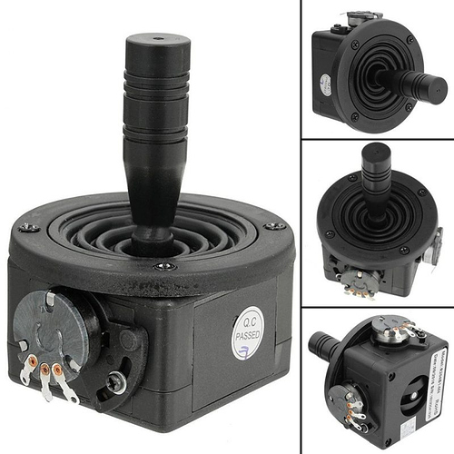
Part resquest: Joystick Part Needed


Hope HM-TRP transceiver

$
0
0

My first go at creating a part. I really just wanted to draw up a neat circuit diagram of my subject tracking camera pan/tilt project but I added the Breadboard and PCB info. The modules have funky metric (2mm) pad spacing. Apart from that, the modules are pretty easy to work with. Details here:-

hoperf.com/modules/lora/HM-TRP.htmlHM-TRP Transciever.fzpz (8.1 KB)

2 posts - 2 participants

Read full topic

TFT LCD screen ILI9341, 2.4-inch SPI, Touch-enabled

Is it possible to make the wires thinner in breadboard view?

$
0
0

Right now it looks like this, but if I add some more sensors to the schematics it is going to be a chaos with this thick wires.

1 post - 1 participant

Read full topic

DIP - ZIP 48 pin for Atmega/Attiny micro

$
0
0

Dear all,

does anyone designed the dip-zip socket *.fzpz? I need a 48 pin (24 per row).

2.54mm pin distance and 3.0" width (the ones to program micro as AtTiny or AtMega.

Could you provide it please?

Thank you
Andrea

2 posts - 2 participants

Read full topic

Raspberry Pi Door Pi

$
0
0

So I’ve been working on my own project to control my door with my Pi.

With a lot of thanks to people on this forum I should say!

It’s mostly there now (I hope).

I’ve made a couple of connector parts that seem to be quite accurate.

The problem I face now is that as per @vanepp advice I’m using ‘thin’ (16mil) traces to get around the raspberry pi header. I found though it still needed a bit of help, so I want to extend the height of the PCB so that traces can go on all sides of the header itself, but I don’t know how to extend the PCB size - it seems locked.

Secondly the DRC brings up a whole load of errors, which I’m mythed by on account that it was the autoroute wizzard that did the routing.

I’m honestly at a loss as to why the autorouting (all be it with ‘thin’ traces) should collide as the DRC claims.

Could someone have a look for me please? If you neaten up the PCB traces too that would be absolutely epic!

Thanks very much indeed.

I’m truly excited to have my first PCB fabricated soon!

Oh, also the strike, bell and 12v-5v may take more than a thin trace can handle, so the path from the DC jack to them may need to be increased, I’ll run the number on that now to be sure.

Door Pi.fzz (156.9 KB)

James.

2 posts - 1 participant

Read full topic

No part search in 0.9.4

$
0
0

Hi,
First post here.

I just installed v0.9.4 and don’t seem to be able to search for parts. There is no search button at the bottom of the Core Parts window.

This seems to be a recurring issue and I’ve tried all the suggestions in the previous posts - giving it permissions in AV, deleting everything and unzipping again and so on.

This is my first time with Fritzing so it’s possible I’m doing something wrong.

Any suggestions gratefully accepted.

Thanks.

Running Windows 10 1909.

3 posts - 2 participants

Read full topic

What tool for connection diagram - MAX485 I2C PCA9685 MCP23017 ULN2803 JMRI CMRI

$
0
0

I am in process of building a HO model train layout, controlled by JMRI via DCC++ and CMRI. For accessory control, RS485 is used to connect Raspberry Pi 3b to multiple Arduinos (i.e., CMRI). I2C is used to connect PCA9685 modules to Arduinos. Turnout switch machine servos are connected to PCA9685 board. I2C also connects to MCP23017 module with ULN2803 for LEDs and/or relays.

I plan to use available modules as much as possible, but I did not locate them in the parts library. Is Fritzing the right tool to create the connection diagram?

  1. CH340g USB to RS485 485 Converter Adapter Module
  2. MAX485 Chip TTL to RS-485 Module
  3. PCA9685 16 Channel PWM Servo I2C Module
  4. MCP23017 I2C 16bit I/O Extension Module

1 post - 1 participant

Read full topic


Add MQ135 to frtizing

$
0
0

Hi all
I need to add MQ135 to frtizing, since I use it for a school project. I’ve searched for it, but only an MQ for MQ3, 4, 6 and 7.
Thanks a lot

2 posts - 2 participants

Read full topic

Taiway sub min dpdt toggle switch

Windows 7 32 bits

DFROBOT Intelligent 10DOF AHRS v1.0

Schematic view - custom parts value display

$
0
0

Hi all!

I created a couple of custom capacitors because I need a couple of them to be horizontally mounted on the pcb board. Typical electrolytic capacitors with both leads exiting the same end of the case, leads bent 90 degrees, so the cap lies flat on the pcb. So I created .svg files for the pcb view for my parts, with the copper holes and a silkscreen rectangle of the size capacitor’s case.

I used fritzing’s standard electrolytic capacitor and in the parts editor, I loaded in my pcb .svg file and changed some settings (capacitance/voltage), and saved new part. The new part works fine, but in the schematic view, the capacitance/voltage values that are usually displayed by the part’s label are missing. Right clicking on the label in schematic view brings up a menu where I can turn on display of those values. Save file and re-open, and the values are gone and have to be turned on again.

Is there anyway to turn on the display of these values so it’s default like the fritzing core parts?

Thanks,
Randy

2 posts - 2 participants

Read full topic

Ask for UTC1117 part

$
0
0

I found that in the core, there was 7805 voltage regulator for 5v, there was no 3.3v edition, also there was a down-pull menu, it could not be selected. And, when I selected 7805, I couldn’t modified it’s pins arrangement as UTC1117.

7805 pins: In Gnd Out
UTC1117: Gnd OUt In

There was a 3.3v in Sparkfun-PowerIC, but the mark “78xxl” couldn’t be changed.

1 post - 1 participant

Read full topic

Routing under a connector

$
0
0

Hello,
I designed my first PCB with Fritzing and I got it produced. When it came it was wrong. I have a connector, a simple female pin header with 4 pins. When I asked Fritzing to design the PCB I did not realize that a track connecting two pins was passing right under the connector, thus connecting all the pins in between. Clicking on the pins in Fritzing was showing the right connections, but the PCB got produced with the holes of the intervening pin passing right to the track, creating an unwanted connection. It seems that Fritzing is not able to avoid the connector holes when autorouting. Or did I something wrong? This was my first circuit (and now I am really frustrated!). Thanks in advance for your help. Best regards,

Federico Carminati

2 posts - 2 participants

Read full topic


Request for Sparkfun 12070 breadboard

$
0
0

Hello,

Does anyone have a Fritz file for a Sparkfun 12070 breadboard that they could share ?

Thanks,
Mike

1 post - 1 participant

Read full topic

Custom part not exporting to .fzpz

$
0
0

I made a custom part, all 3 views (Breadboard, Schematic, PCB) look and work fine in Fritzing but exporting as .fzpz is not working.

No error, or warning.

Any ideas?

Thank you.

2 posts - 2 participants

Read full topic

Installion Instruction

$
0
0

Hello,
I was using the version 0.9.3b from Ubuntu Software and then decided to update it with version 0.9.4, I have downloaded the tar file from github and now i don’t know how to install this to my system, i tried with terminal by typing “./fritzing” but it said no file or directory.

edit1: I figured it out but now it throws second error as :slight_smile:

2 posts - 2 participants

Read full topic

Installation Procedure {Linux}

$
0
0

{Tested and Working on Ubuntu 20.04 LTS} {Fritzing 0.9.4}

Hello!
I’ll show you a described way to install Fritzing on your Linux machine with less hassle.

Let’s Start with Downloading the most recent version!
Here:- https://fritzing.org/download/

  • Select your System on which you want to install it.

  • Next save it in your desired location.

  • Open the downloaded Archive and extract it to ~/Fritzing
    {This basically means your Home directory}

  • Open your terminal in that folder and run the software by using command: ./Fritzing

Problems You might face:

  • While running for the first time, It might look like stuck on splash screen.
    Do not close or kill it, it will lead to a Library Corruption, Instead allow it to run for a while, as it is pulling updates from Github Repo.

  • Open executing Fritzing from terminal using ./Fritzing , Throws this error:-

Solution:- This means that you don’t have the libraries or Fritzing is just unable to find them for some reason. Execute the following commands in terminal:

sudo apt-get update
sudo apt-get upgrade
sudo apt install libqt5printsupport5 libqt5xml5 libqt5sql5 libqt5serialport5 libqt5sql5-sqlite

It will install the required library if missing, and you’re good to go!

  • Installing with sudo apt-get install fritzing ?
    It will install and older version of Fritzing 0.9.3b and i recommend you to download the recent from the webpage : https://fritzing.org/download/

Thank you for Reading,
Shigarf :grin:

Posted: 2020-05-28T18:30:00Z
Edited: N/A

1 post - 1 participant

Read full topic

Cable Designatoins in Fritzing

$
0
0

Hello. Is there a way to do “Connector and Interunit Cable Designations”?
Like in the attached image.

For now I’ll just have a dummy part with ‘W’ as the RefDes and a note of what the cable is.

5 posts - 2 participants

Read full topic

Viewing all 5447 articles
Browse latest View live


<script src="https://jsc.adskeeper.com/r/s/rssing.com.1596347.js" async> </script>