Quantcast
Channel: fritzing forum - Latest topics
Viewing all 5416 articles
Browse latest View live

IC Component CReation

$
0
0

@isteward wrote:

I have used Fritzing successfully for through hole projects but now I need to create a surface mount board. I cannot find any way to find(search) for a 44 pin QFN design for IC. Can you tell me if this is possible or not.

FYI - This is for IC PIC24FJ128GA204

Posts: 2

Participants: 2

Read full topic


Large Warhammer 40k Model Lighting Project Help

$
0
0

@Haversack wrote:

Hello all!

New here. Just getting into this stuff and I’ve bungled my way through tutorials on Adafruit and I’m now gearing up for the project I started learning this for. I’ve gotten to the step of hooking/soldering everything together and made a diagram in fritzing. I could use some help/verification that I’m barking up the right tree and doing things correctly.

I’m attempting to make a model interactable/light up. Google Forgeworld Warbringer Nemesis to see the model in question(Since I’m limited on images & links apparently).

Current Parts list:

  • Adafruit Feather M0 Bluefruit LE
  • Adafruit 12-Key Capacitive Touch Sensor Breakout - MPR121
  • NeoPixel Nano 2427 RGB LEDs w/ Integrated Driver Chip
  • NeoPixel Diffused 5mm Through-Hole LED
  • Continuous Rotation Micro Servo - FS90R
  • Half Size Breadboard + 78 Piece 22AWG Jumper Wire Bundle(https://www.adafruit.com/product/3314)

So the idea is to light the body/torso of the model with roughly 6 LEDs and have each arm lit with at least one LED, or in the case of the gatling gun, have the servo hooked up so it can spin. Each gun/arm should have detachable connectors so other weapons can be swapped in.

I’m planning on placing capacitive touch points all over the model to control the state of different parts. I’m going to try the conductive paint to see how it works and if it doesn’t I’ve bought some copper tape.

I’ve mostly prepped the model. Now I’m working on the wiring so I can test the setup before gluing everything in place and painting.

Here is the Diagram and project file. Not sure I’ve done what is necessary and I’m still learning terms. I have not added in the servo, but the intention is to make it so either arm can swap to it.

Hopefully this is the right file.
Warbringer Sketches.fzz (171.2 KB)

Any help/advice/tutorial links are much appreciated!

Posts: 2

Participants: 2

Read full topic

Anyone attending FOSDEM2020

$
0
0

@cmbahadir wrote:

Hello There,

Is there anyone who is going to be at FOSDEM2020, Brussels this weekend?

We can get together and have a coffee(or tea, or beer, or water …) :slight_smile:

Posts: 1

Participants: 1

Read full topic

Can't assign pins in the Parts Editor

$
0
0

@MX39 wrote:

I tried updating an IRF520 MosFet part, because it doesn’t show all its connectors in the curcuit board view.

I modified the SVG using notepad++ and it’s importing “without” errors.
This is how it looks like right after importing to fritzing:

However, the pins for V+, V-, VIN and GND are assigned to something that doesn’t exist.
I somehow can’t fix that by using the “select graphic” button as it won’t show the dotted lines after clicking on the correct circle. (scrolling through the layers using SHIFT+MouseWheel)

I’m using fritzing 0.9.4 64bit on Windows10 Pro build2004 64bit, but also tried 0.9.3 64bit.

Posts: 2

Participants: 2

Read full topic

Compiler problem: switch statement

$
0
0

@ayeshasalman wrote:

Hi Guys This is Ayesha It has been long time that I’m working on a project of arduino and I have searched my question here and there but couldn’t find it. Well let me explain the issue I’m getting with my arduino switch and its timing.

I believe the arduino that I got from an online electronic store as i think it’s SWITCH statement has some compile time problems.

If I try to declare a boolean variable in a CASE statement as illustrated in "case 2: in the snippet below, the compiler throws an error.

I add this to the other CASE statement problem I flagged earlier: ie. the compiler does not throw an error if you misspell “default” as “defalut.”)

CODE

switch (var) {
case 1:
//do something when var equals 1
break;
case 2:
boolean X;
//do something when var equals 2
break;
default:
// if nothing else matches, do the default
// default is optional
break;
}

This appears to be a problem with the compiler, NOT my code, and it seems to happen only with nested SWITCH statements.

Thank in advance for your prompt response

Posts: 1

Participants: 1

Read full topic

Heltec Dev Boards

$
0
0

@UniquePete wrote:

Here are some Heltec (and a couple of other) Dev Board parts that I created recently. I’ve run them all through the Parts Checker, so at that level they should all be OK, but I’ve not yet been able to get them through the GitHub checking process so I thought I’d just post them here in the interim.

Amica NodeMCU DevKit.fzpz (50.7 KB)
Elecrow ESP-WROOM-32.fzpz (51.7 KB)
Heltec CubeCell Dev-Board.fzpz (54.5 KB)
Heltec WiFi LoRa 32 V2.fzpz (58.3 KB)
Heltec WiFi LoRa 32.fzpz (39.1 KB)
Heltec Wireless Stick Lite.fzpz (66.1 KB)
Heltec Wireless Stick.fzpz (82.6 KB)

Posts: 1

Participants: 1

Read full topic

3-pin DC motor 5V

Using property names in part creation

$
0
0

@microMerlin wrote:

I am creating a family of parts. In the process, I am setting up several properties that allow the user to switch between the parts from the inspector. I have a size that switches between 4 sizes, a pcb pad that switches between 2 pcb footprints, a variant that switches between 2 polarities. That is all working. I also included a part number without any value, that allows a value to be entered in the inspector. Also working. Then the part that does not work. I wanted to have another property that, like part number, creates a text box in inspector to let the user fill in a value. I tried color and led color names, setting them up the same as part number. However, inspector just shows them as a read only empty value. No box, no drop down. Is there something more I need to do to create a property name that acts like part number? Are the rules for using fzp properties and property names documented somewhere?

Posts: 10

Participants: 2

Read full topic


HELP updated fritzing lost all my files

$
0
0

@daandoeleman wrote:

I updated and lost all my projects :frowning:

the fritzing map on windows documents is empty

Is there a way to get them back?

Posts: 2

Participants: 2

Read full topic

Searching for lm383

Custom Shaped PCB crashing output

$
0
0

@Time_Wolf wrote:

Every time I try to generate an extended Gerber PCB, fritzing just sits on screen showing nothing.
However, if I go into finder (OSX 10.14.2) I find all the files except for the drill file.
Is there a log file anyware I can check to see what happening or does anyone know of a walkaround/fix for this?

My version of Fritzing and my operating system:

Frizing 0.94
OSX 10.14.2kitsune badge.fzz (31.7 KB) Screenshot 2020-02-09 at 12.05.51
Please also attach any files that help explaining this problem

Posts: 7

Participants: 2

Read full topic

SK6812 RGB LED parts

$
0
0

@Time_Wolf wrote:

Is anyone working on Parts for the SK6812 range of RGB LEDs?
I’m i need of the 3030 package, 4020 package and the mini E package please.

Posts: 10

Participants: 2

Read full topic

Doit esp32 devkit v1 30-pin

$
0
0

@Rene65 wrote:

Does anybody has a friting part of the esp32-wroom Doit esp32 devkit v1 with 30 pins???
It’s a little wider than the esp8266 wemos d1

Posts: 2

Participants: 2

Read full topic

New Part THT & SMD problem

$
0
0

@Blue wrote:

Hello,
I was checking my old parts, then I noticed this problem…

I created a USB socket part, that has “SMD” pads & “THT” pins for terminals…
Now, those pins are acting differently…!!!

THT should accept the trace top & bottom, & SMD only the part side.
But, both are acting like SMD, also, changing part layer, make the part useless…

This type of part is rare… I found only one… (can’t be exported)
2020-02-10

First, I thought, It only works with core part… But I manage to find those original file & save as new part…
And it is working…
111.fzpz (7.9 KB)

I follow everything with this file… But my part is not working, even terminals got messed up…

My part as posted before: 46. USB-A Male SMD.fzpz (9.8 KB)
My part messed up after follow the core part: USB-A Male SMD [edit].fzpz (7.8 KB)

So, if anyone can check this out, and find the problem, that’ll be very helpful…
cause, I have two other parts to edit/repair this way…


Thanks…

Posts: 8

Participants: 2

Read full topic

How can I add a voltage regulator LM2678

$
0
0

@mepuli wrote:

Hello I need to create an schematic with a voltage regulator LM2678 NDZ Package 7-Pin TO-220, but I don’t know how to add it. I could not find it

Posts: 3

Participants: 2

Read full topic


Part update pcb view mess, possible corruption in sketch

$
0
0

@microMerlin wrote:

Testing the update process for a part being obsoleted worked with a simplified test sketch, but a slightly more realistic sketch lost connections and traces in the pcb. There was a bit of minor cleanup needed on the breadboard view, that amounted to moving breadboard and updated part slightly to get them to reconnect. Schematic view updated fine.

@vanepp I figured this belonged in its own topic. Probably nothing to do with property names :slight_smile:

The sample drawing and update were done using Fritzing 0.9.4b commit c595162a1d0 on a full up to date Fedora 31 workstation.

Here is what the pcb view looks like before the led matrix part is obsoleted. Don’t try to make sense of that as normal pcb. This was for an experiment to mount the controller chip directly on the back of the led matrix, and use direct point to point wirewraping instead of pcp traces. This just provides a visual tool for planning the wirewrap connections. Though I was pleased to find I could layout the pcb with only a single via.

Here is what it looks like after the part was obsoleted, the sketch reloaded, and the part updated. All connections are now ratsnest lines, and many of the traces (especially top) are missing. Others are missing from some of the bend points.

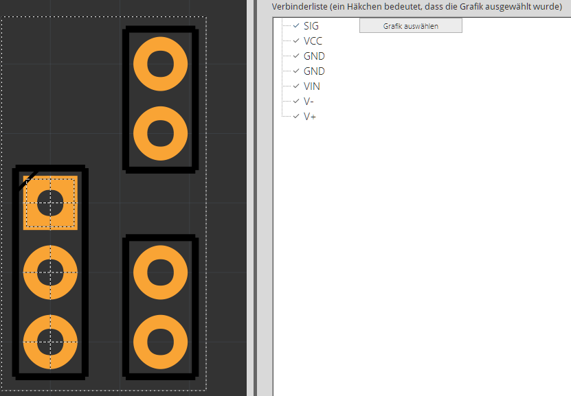
Here is what it looks like with the led matrix part moved left 0.1 inch and down 0.2 inches, showing that the traces that remain are not actually connected to the part.

Attached is the drawing, from before the update was done. To replicate the steps, you will need to use the 8x8_led_matrix branch of my fritzing-parts repository. That is where both the new parts, and the obsolete LBT2088ah part exist.

LBT2088AH test.fzz (28.0 KB)

git clone https://github.com/mMerlin/fritzing-parts.git --branch 8x8_led_matrix

Anyone have ideas on what would cause that sort of breakage, when both the new and obsoleted part have been shown to work in a simpler drawing?

test-orig-master.fzz (8.7 KB)

Extra information. Many of the open ended circuit traces only partly exist. Trying to move the end point, or add a bend point causes them to vanish. The board design was done in the schematic view, except for JP1. That was connected after most of the pcb board routing was finished, and it became obvious which connections would most easily reach which pin. There isn’t really a molex connector there. Just a bundle of wires going off board.

Posts: 1

Participants: 1

Read full topic

Can´t find chip ESP32-WROOM and ESP32-WROVER

$
0
0

@ToDa wrote:

Hi
i´m looking for a new popular microcontroller from Espressif that i have made som really fancy stuff with. I can´t fint this in the libary.

Anyone that can support making the chip ESP32-WROOM and ESP32-WROVER ?

product information of ESP Modules

Thanks

Posts: 1

Participants: 1

Read full topic

5 pin XLR not found

I need a power supply

Looking for a usb Mini B connector non smd

Viewing all 5416 articles
Browse latest View live


<script src="https://jsc.adskeeper.com/r/s/rssing.com.1596347.js" async> </script>