Quantcast
Channel: fritzing forum - Latest topics
Viewing all 5447 articles
Browse latest View live

Small Transformer 14x19x15h

$
0
0

@Old_Grey wrote:

I don’t know if anyone would want this because they seam to be non existent these days.

Small Transformer - 14mm sq core - 19mm wide - 15mm high - 2 Primary pins - 3 Secondary pins
v1 - Transformer.fzpz (8.8 KB)

EDIT - I moved this part here because the original was mainly talking about a LED Timing Light.

Posts: 1

Participants: 1

Read full topic


Export creates distorted PCB

$
0
0

@Vitesze wrote:

I made a PCB design and am trying to export it (RS-274X). However, for some reason the Gerber design becomes distorted when I submit it for production with Seeedstudio.

Image 1 - my original design in Fritzing
Image 2 - the resulting Gerber file, opened in Seeedstudio

Untitled2

What is this issue caused by? I tried resizing my PCB and moving components but the left side continues to be distorted. The board and both silkscreen layers I designed in Inkscape look perfectly fine.

Posts: 3

Participants: 2

Read full topic

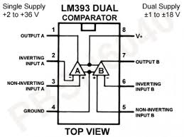
LM393N Dual Comparator Op Amp

LM741 Single Operational amplifier

4116R-001-750 Inline resistor ic chip package

Molex computer connector

$
0
0

@traisjames wrote:

I may be wrong, but it seems like the Molex 4 pin Computer Connectors are backward. Looking at the Male connector/female pin plug that comes from the power supply, with the flat side down and the top slide with slopes up, is that it goes 12V-N-N-5V. When I use the Sparkfun Molex Vertical connector, says 5V-N-N-12V. Am I missing something or is there an error?

Posts: 2

Participants: 2

Read full topic

Part image is visible in Editor but not Sketch

$
0
0

@beachboy wrote:

I imported the pin header from this post http://forum.fritzing.org/t/raspberry-pi-40pin-header/2108 into inkscape and added an .svg image with pin descriptions. I brought the resulting file into Fritzing Parts editor and it looked and acted as expected. But when using the part in a sketch the description image is not visible as in the screen shot below. I attempted to up load the file and screenshot but ,as a new user, can only upload one item so I could try to provide the file if necessary.

Posts: 17

Participants: 2

Read full topic

Project won't load

$
0
0

@dhlii wrote:

I get an error that says there is “no sketch found” in the project directoy

I can unzip the project and all the parts files are present.

How can I recover the project ?

Posts: 1

Participants: 1

Read full topic


I cannot find a part

$
0
0

@ps56 wrote:

I cannot find a Silicon Controlled Rectifier part in the core parts or in any other place
.:disappointed_relieved:

Posts: 1

Participants: 1

Read full topic

Incorrect Auto Route for 7 Segment Display

$
0
0

@Wolf66 wrote:

i just created a simple circuit which includes 5 pcs 74HC595 shift register and 5 pcs 7 segment displays. Since i live in Austria i need to buy the 7 segment displays on the local market. The order of the connections is different to the ones from the fritzing library. Here is my problem:
Even though i connected the 7 segment displays correctly on the bread board page the autorouting is ignoring it and creates wrong connections on the cicuit. E.A. my 7 segment display have the common cathode on 3 and 8. But the circuit autoroutes them to 9. The segments as well are wrong routed.

I even tried to change the connections in the parts editor but it gets completely ignored.

Mini Scoreboard V2018.fzz (58.2 KB)

Any idea what i am doing wrong?
Thx in advance

Posts: 2

Participants: 2

Read full topic

74LS148N - 8 to 3 bit - Priority Encoder

First PCB design feedback

$
0
0

@Tverberne wrote:

Hello,
I’m already a user of arduino and IOT devices but making a pcb is new for me.
I tried to make a small pcb for my IOT system.
It contains a ESP8266-01, DHT22, LDR (includes 10K resistor) and reset button.
Power supply = 9V with 2 voltage regulators: 5V and 3,3V

Is there somebody who wants to help me by checking my first PCB design and give me feedback?

Timo
LDR ESP8266 PCB.fzz (25.6 KB)

Posts: 1

Participants: 1

Read full topic

Fritzing.0.9.3b.64.pc just hangs on Windows 10

$
0
0

@bcraigie wrote:

Steps I took that resulted in the problem:

I was informed there is a parts update. After a long time the parts update had downloaded, but had not completed, and fritzing appeared to be hung. I had to reboot the computer. Now Fritzing just hangs after opening up (“Not responding” - using about 20% cpu, but apparently not doing anything)

What I expected should have happened instead:

Should not have hung. Should display any progress so we know if it is actually doing something, and regular progress updates would mean Windows would not think it is not responding. But… how do I now cure the hang? :slight_smile:

My version of Fritzing and my operating system:

fritzing.0.9.3b.64.pc
Windows 10 1803 (Build 17666.1000)

Please also attach any files that help explaining this problem

Posts: 5

Participants: 2

Read full topic

PHPT61002NYCX part

Weird connection - Help into my final project

$
0
0

@QuantumHK wrote:

Hi, i just make a small circuit which detects electromagnetic fields using mosfet and BJT transistors, I just bought the pieces and i am waiting for them to start testing at the real life, so advancing in my report i downloaded fritzing to draw my project, after i finished drawing all seems to be good, instead of the 1 gigaohm resistor, i don’t know what’s that weird connection, can anyone help me? the schematic and the breadboard prototypes are in the file .fzz, I’ll also add an image of my original circuit. thank you.

PROYECTO.fzz (10.8 KB)

Posts: 2

Participants: 2

Read full topic


Cheap digital compass module using BMC5883L

Remove profile and project

Non consecutive Connector ID when adding more connectors in New Parts Editor

$
0
0

@gerrikoio wrote:

Steps I took that resulted in the problem:

Open up any part (e.g. generic female header) in New Parts Editor and click on Connectors tab.

You will see in top edit box number of connectors = 2.

Below you will see

id: connector0 for pin 1
and id: connector1 for pin 2

Now increase the number of connectors to say = 10

What you now see for pin 3 is a connector id = connector3 instead of connector2

What I expected should have happened instead:

It is a non-consecutive increase. It should be connector 2

My version of Fritzing and my operating system:

…Version 0.9.3 (b5c895d327c44a3114e5fcc9d8260daf0

Please also attach any files that help explaining this problem

This problem can only be replicated in Parts Editor.

I have spent weeks creating a part which has more than 64 connectors.

I cannot now find a way to get the connector ids to match because parts editor cannot count properly. This is such a basic error that can so easily be fixed. I am just surprised it hasn’t been sorted by now and is not seen as top priority.

Posts: 3

Participants: 2

Read full topic

Where is my GDPR email

$
0
0

@gerrikoio wrote:

I have not received any GDPR email from Fritzing or the Fritzing forum. Who is responsible. Someone best get on to it pronto.

Posts: 4

Participants: 3

Read full topic

Cypress PSoC 6 BLE Pioneer Board

Viewing all 5447 articles
Browse latest View live


<script src="https://jsc.adskeeper.com/r/s/rssing.com.1596347.js" async> </script>