Hi,
New to Fritzing, but have successfully created a board.
However, I want to modify some existing parts using InkScape. But for some reason the image for PCB-view of the part is not saving in InkScape as expected. (BB and schematic views are OK).
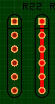
See image below from PCB-viiew in Fritzing.
This example is the resistorpack in the core-bin. Five resistors in the same package.
The left part is the original PCB-image, it's OK. The right part is after opening the image in InkScape and just saving it again.
There's a thick red line in the image saved with InkScape 
Same problem with all parts I have tested.
- SVG-Images extracted from the original parts fzp-file. No problem there.
- InkScape 0.92 Fritzing 0.9.3b
- Image saved as plain SVG in InkScape..
- In InkScape it looks OK. But In Fritzing PCB-view there is this extra red line.
And also it's not possible to move the part in Fritzing.
No matter where you click in the image, you only start a new wire.
- Connectors looks OK when viewing images in Fritzing.
- When comparing old/new file with the XML-editor in InkScape. Copper0 and Copper1 looks the same to me.
- The size of the file after saving in InkScape is almost twice the original (no editing done). Is this normal ?
- I used an external XML-editor to compare the SVG-files before/after saving, and the formatting looks completely different ?
Files in InkScape should be saved as plain SVG. But are there more to think about ?
(I tried uploading the two SVG-files. But it says that the size cannot be determined ?)
![]()