Quantcast
Channel: fritzing forum - Latest topics
Viewing all 5657 articles
Browse latest View live

Introduction : Vj Dobermann

$
0
0

@vj_dobermann wrote:

Hi everybody,

I introduce myself :
Vj Dobermann aka Joel, I'm video-jockey since 2004 for any types of events in Switzerland and France and I also compose psy-trance music.
Sometime for my dance school, I create some arduino projects, the last one was a light suit with EL wire.
My next arduino project consist of a heartbeat captor connected to Ableton Live to send audio clips.

I hope I'll find some support on this forum :slight_smile:

Joel

Posts: 1

Participants: 1

Read full topic


How shall I get a perfboard/matrix board view?

Obstacle avoidance IR Sensor module for fritzing

$
0
0

@sandtrap777 wrote:

Hey everyone,

I've been searching everywhere for the Obstacle avoidance IR Sensor module for fritzing without any luck. Would someone know where I can get it?
Thank you for your help

Posts: 4

Participants: 2

Read full topic

I need a relay ky-1 please help me

4x5 Key switch pad with LEDs (YL-4)

$
0
0

@vk2qz wrote:

Hi all,

Does anyone have a part already created for the YL-4 which is a 4x5 switch matrix with 8 LEDs identified as YL-4 ?

It's an old part but ideal for my use.

If not, I'll have a go at creating it.

Thanks

Posts: 1

Participants: 1

Read full topic

FC-51 Infrared Obstacle Avoidance Proximity Sensors Module

$
0
0

@vanepp wrote:

To my suprise there was no part for this common ebay module, nor for the right angle male .1 header that it uses (which was the most difficult part of this to make :slight_smile: ) so I corrected that. All three views although PCB is minimal.

fc-51.fzpz (21.2 KB)

Peter

Posts: 1

Participants: 1

Read full topic

PCB to 3D Printed Cases

$
0
0

@smilliken wrote:

I've been working on a project that encompasses the following parts,

  • PaPiRus 2" screen, RPi Zero v1.3, Adafruit Powerbooster 1000c and a 1200 mAh battery.

I is a bit of a thick bundle and I'm looking for a case to hold all of the components.

I was hoping that this knowledgeable group of people here might be able to steer me in the correct direction.

The question is, how can I/do I go from the physical being to a 3D (.stl) files to print out a case. I realize I probably need some software. I do have OpenSCAD installed, but I don't have a 3D scanner to use.

Is there a way to import the dimensions of the boards into a software program to try and build something?

Any questions welcomed.

Thanks

Scott

Posts: 1

Participants: 1

Read full topic

Question on caps

$
0
0

@JGwinner wrote:

Hi. I've checked the tutorials and parts help, but am slightly confused.

Most of the caps have a TON of variations, but I can't relate those to common parts sites, such as Mouser. For example, I'm trying to use a 220uf Aluminum cap with say 3.5mm lead spacing. That seems fairly straight forward.

Yet, when I do a search, and drag a cap on the schematic, it has variants like panasonic_c, _d, _e, _g and of course a note I should check the hole spacing. Ok, I got that - but how? What do these other package and variants represent? Panasonic's own data sheets don't seem to have lists of these variants.

It's like I need a rosetta stone :slight_smile:

I know it's not a huge deal, these are common parts, but I'd like to be able to build a proper BOM.

Thanks, hope this isn't too much of a n00b question.

== John ==

Posts: 3

Participants: 2

Read full topic


PC-Monitoring Board / Shift-Registers and Optocouplers Question

$
0
0

@martinJhenne wrote:

Hi all,

as a beginner i am trying to make a pcb-board that extends a raspberry and can connect to different PCs for resetting, power controling and monitoring the power led. I also want to add a temperature sensor. To save pins on the raspberry and to make the project modular i used shift registers.

I would be glad if someone could have a look at the schematics and check for errors. I am not sure if resistors are missing or have the wrong value!

I will release the project on github if it works :slight_smile:

monitoring_0713.fzz (53.3 KB)

Posts: 2

Participants: 2

Read full topic

Help a developer wannabee?

$
0
0

@vanepp wrote:

I'm trying to become really dangerous and start looking over the source code to see if I'm able to help. The answer so far is no, I can't even get the .9.3.b release to compile. I have a Ubuntu 16.04. LTS system up and running, have run through all the prereques, given up on Qtcreator (which is just plain broken on my system apparantly) and done a command line compile of the current head. That sails along nicely til it gets in to partschecker.ccp at which time recipe for target release failed comes up. Same thing happens on the .9.3.b release branch code, so I'm fairly sure its something I'm doing rather than the code. Can anyone suggest what I'm doing wrong please?

Peter

Posts: 1

Participants: 1

Read full topic

Modifying generic IC pins

$
0
0

@mahmood wrote:

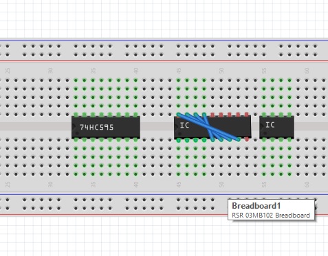
With the latest version, 0.9.3b, I put a generic IC on the breadboard and the then go to Inspector->Pins and change the default 8 to 16. However, the result sounds messy! Please look at the picture and you will see some wire exchanges and also the green dots (to show connected holes) are not present. What does that mean? Did I miss some steps to enlarge a generic IC (from 8 to 16)?

Posts: 1

Participants: 1

Read full topic

Design layout for custom perfboard

$
0
0

@ttsiodras wrote:

First-time user of fritzing here - hi, folks.

I recently bought a custom perfboard. How would I go about creating it as a "template" for use in fritzing?

The closest I could get by default was to set the proper number of holes (20x36 - since I had to include the space for the ones that are used for power and ground lines - see photo)

But the layout is neither horizontal nor vertical strips - it's both, as you can see.

How can I create that layout in fritzing? Any pointers/videos?

Any help much appreciated - I'll upload the layout on my site for others to re-use, if I end up being able to make it.

UPDATE: This seems to be related, from the Fritzing source repo:

Can anyone explain the format used here? I could in theory programmatically create the related file for my perfboard.

Posts: 1

Participants: 1

Read full topic

5 x 20mm glass fuse holder

$
0
0

@Bergerie wrote:

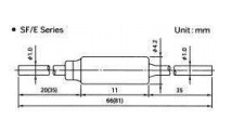
I'm looking for a 5 x 20 mm glass fuse holder fritzing part for which the attached spec sheet applies. Anyone able to avail or create?
Rgds
Dick

Posts: 3

Participants: 2

Read full topic

Afficheur 7 segments 4 digits

$
0
0

@fanfan_84 wrote:

bonjour tout le monde,
je suis novice avec arduino et je bute sur un truc.

je souhaite faire un compteur avec 4 digits.
le câblage est bon mais lors de l'exécution du code les 4 digits restent allumés.

je vois que cela incrémente bien mais les chiffres se voient à peine.

je m'explique : les chiffres s'allume complètement, on voit un 8 avec point décimal.
lors du comptage le chiffre change mais je vois toujours le 8 affiché. un faible scintillement apparaît.

j'ai essayé de changer la valeur de " setBrightness " mais cela change rien .

quelqu'un pourrait me donner une idée ???

voici mon code :slight_smile:

include "SevSeg.h"

SevSeg sevseg;

int pinA = 9;
int pinB = 8;
int pinC = 7;
int pinD = 6;
int pinE = 5;
int pinF = 4;
int pinG = 3;
int pinDP = 2;

int DIG1 = 13;
int DIG2 = 12;
int DIG3 = 11;
int DIG4 = 10;

void setup()
{
byte numDigits = 4; // Nombre de digits
byte digitPins[] = {13,12,11,10}; // digit de 1 a 4
byte segmentPins[] = {2, 3, 4, 5, 6, 7, 8, 9}; // Branchements des Pins

sevseg.begin(COMMON_ANODE, numDigits, digitPins, segmentPins);
sevseg.setBrightness(20);

pinMode(DIG1, OUTPUT); // pin 13
pinMode(DIG2, OUTPUT); // pin 12
pinMode(DIG3, OUTPUT); // pin 11
pinMode(DIG4, OUTPUT); // pin 10

pinMode(pinA, OUTPUT); // pin 9
pinMode(pinB, OUTPUT); // pin 8
pinMode(pinC, OUTPUT); // pin 7
pinMode(pinD, OUTPUT); // pin 6
pinMode(pinE, OUTPUT); // pin 5
pinMode(pinF, OUTPUT); // pin 4
pinMode(pinG, OUTPUT); // pin 3
pinMode(pinDP, OUTPUT); // pin 2

}

void loop()
{
// digitalWrite(DIG1, 0);
// digitalWrite(DIG2, 0);
// digitalWrite(DIG3, 0);
// digitalWrite(DIG4, 0);

static unsigned long timer = millis();
static int deciSeconds = 0;

if (millis() >= timer) {
deciSeconds++; // 100 milliSeconds = 1 seconde
timer += 100;
if (deciSeconds == 10000) { // Reset apres 1000 seconds
deciSeconds=0;
}
sevseg.setNumber(deciSeconds, 1);
}

sevseg.refreshDisplay();
}

Posts: 8

Participants: 2

Read full topic

Auto Save (Help or Hinder)

$
0
0

@sublimeartistry wrote:

So I look to have lost a huge deal of work and I am wondering if Auto save may have saved me or has caused the problem.

My question is what does auto save do? Does it save over your existing file or is it creating a temp saved file somewhere on my system?

My file was about 900kB and now it is only 22bytes (last save was friday morning before playing with the development version) . I do have older versions of the file but they are all at least 2 weeks old and missing all the tiny changes i've made while testing my prototype boards over those 2 weeks. If Auto save has written over the file and caused the problem then I will be stuck trying to remember the values I have changed and small changes that would have made it easier to assemble.

Posts: 5

Participants: 3

Read full topic


Thermal Fuse Fritzing Part

$
0
0

@Bergerie wrote:

I'm looking for a part which resembles closely the PCB requirements of a thermal fuse type SF70E. It has a 1mm lead thickness. Anyone having it available or could direct me to a similar PCB part?

Rgds
Dick

Posts: 3

Participants: 2

Read full topic

From Prototype to Product

$
0
0

@marcoss wrote:

Hi,

I have a working prototype and want to make it as small as possible.
Please, see the image in attachment.
The device is attached to a beach racket and is used for game play measurements.

This is the list of components:
- Arduino Nano
- KY-038 microphone (to sense the ball hit)
- SW-420 vibration sensor (to sense the ball hit)
- NRF24L01 wireless transceiver (for communication with a base station)
- Switch (to set as player A or B)
- A LED (to indicate a hit)

I'm not intending to sell it, and, if I ever do, it will be in very small quantities.
The price is not an important factor but the size and weight are.

What are the recommended steps to make it smaller and smaller?
I accept any kind of recommendations, from changing components, to assembling boards, to sending to a manufacturer, etc...
I'm a computer scientist with little knowledge about electronics.
Is Fritzing the right tool for me? If so, what are the next steps? Reproducing my circuit in the Fritzing breadboard view?

Thank you,
Marcos

Posts: 3

Participants: 3

Read full topic

Inkscape Tips and Tricks

$
0
0

@sublimeartistry wrote:

Just thought I would start a thread to share a few of my tips and tricks to working with Inkscape to produce new parts/boards for Fritzing. (please feel free to add your tips and corrections)

1) Setting up Inkscape.
Set transformation parameters.
Edit/Preferences/Behaviour/Transformations
Disable "Scale Stroke Width" (makes it easier to change size of holes in rings, etc)
Disable "Scale Rounded Corners in Rectangles" (makes adjusting custom PCB size more consistent)
Enable "Optimized" Store Transformations (should be enabled by default and should prevent some extra transformations from being inserted)

2) Removing extra transformations inserted by Inkscape.
Option 1) (Works 100% of the time)
Ungoup objects until they are no longer in a group (Ctrl Shift G repeatedly or Extensions/Arrange/Deep Ungroup) and then Re-group (Ctrl G) and rename the group to its original name.
Option 2) (should work but I have not had the best of luck as it has made some unexpected changes but worth a try)
Use Apply-Transformations extension https://github.com/Klowner/inkscape-applytransforms

3) Repairing Custom PCB with holes. (If Fritzing says your PCB does not have any holes but it should)
Select all board parts while holding shift. (You may need to be in node editing mode not object)
Union all board parts into a single outline (Ctrl +)
Break apart previously unioned board outline (Ctrl Shift K)
Select 2 previously un-unioned paths that should be holes (while holding shift) and union them together (Ctrl +). (You may need to be in node editing mode not object)
Repeat adding hole paths one at a time until all the holes are one object.
Select the board outline and the previously unioned holes while pressing shift and difference them from each other (Ctrl -).
You should now have a Board that Fritzing recognizes as having holes. When you use the board in Fritzing it should tell you that you have 1 hole more than you actually do. (it sees the outer path as a hole plus the actual holes).

4) Resizing all rings equally in Copper layer.
Resize each copper ring individually taking note of the difference in the size (before +/- after)
Move entire copper group half of the difference in size. If you increased the size move the group negative on X and Y (size difference/2). If you decreased the size move the group positive on X and Y (size difference/2).

When I think of more I will add them.

Posts: 1

Participants: 1

Read full topic

Want more parts FAST? Allow Embedded PNG inside SVG

$
0
0

@JayShoe wrote:

Hello,

I know PNG doesn't allow for high resolution scaling. But not all diagrams and designs need to be high resolution "scalable"! I've tested this with Inkscape and it works partially, but has bugs.

Creating the SVG:
1. Open an existing part in inkscape
2. Choose File>Import and select a PNG image of your target part. (hint, copy it from the datasheet).
3. Scale the PNG into the SVG.
4. Add SVG shapes overtop of each pin.
5. Configure the SVG as you normally would in the XML.

I tested this and made a "PEACE IC" and it worked inside of the parts editor. It actually opened inside of Fritzing for a moment (I thought) but I can't reproduce it (it's buggy). See this file: https://drive.google.com/file/d/0B1-njqPoef5AWV9WX2ktcWlYU3c/view?usp=sharing

I have heard a lot of discussion from people that "we need more parts". This solution doesn't produce the shiny new parts that I guess the developers intended. But it would work, and it would be functional. Adding support for this would allow people to rapidly create high quality diagrams on parts not already created.

Jay

Posts: 5

Participants: 3

Read full topic

Solution to Installing problem!

$
0
0

@RiotQuizz wrote:

Hello guys, most of you have had one problem after extracting and installing fritzing with the next message "error api-ms-win-crt-runtime-l1-1-0.dll" Well, it happened the same to me, the only possible solution that I thought at the moment was to download the .dll file but then after downloading and extracting the .dll file I found that when you try to run the program again it gives you another message but with a different .dll file.

The point is that I downloaded every single .dll file and it actually worked.
If you want to try here is the link to get my .zip file containing all the necessary .dll files that i needed, I hope it can help you.

LINK___ https://mega.nz/#!Et1y2SgL!rmHslipct9SWotWqMuEbmdiCJ8F4bN-FSMNeG6yi-xs

It was tested out in a computer with Windows 7 Ultimate 32Bits

Posts: 1

Participants: 1

Read full topic

Viewing all 5657 articles
Browse latest View live


Latest Images