December 17, 2017, 9:17 pm
@bLackburst wrote:
Hi
I'm a first-timer and I'm working on a project with a very short deadline. Could someone please cast their eyes over my project before having it fabricated? Willing to donate for time etc.
Very simple project but tbh I don't really know what I'm doing with fritzing. It's a teensy breakout board for a bunch of analog pins to a 36 pin connector. I know that what I want to build works(I've soldered one manually, just never tried a pcb) so I'm really just concerned with trace contrinuity and best practice.
I tried getting the ground to the gnd pins on the connector using them as ground fill seeds but have ended up using a bunch of vias in an ugly configuration. Will this thing wo
rk? There doesn't seem to be enough room for copper fill points anymore, I would REALLY appreciate some help, this thing needs to be fabricated asap. Thanks heaps.Teensy Breakout.fzz (130.2 KB)PJRC-TEENSY36-BASIC_e0a6edb11f7e2836bb5d93067f5d2499_1.fzp (29.4 KB)
Posts: 1
Participants: 1
Read full topic
↧
December 18, 2017, 10:01 am
↧
↧
December 19, 2017, 9:53 am
@joelbezerrapinho wrote:
Hello,
wanted to know if this fritzing process (400.000) in the task manager is normal
and it's kind of slow
Processor - core 2 duo E8600
Memory - 3gb
Video card - GeForce 256mb - 7300 SE/7200 GS
tanks
Tanks!
Posts: 3
Participants: 3
Read full topic
↧
December 19, 2017, 3:13 pm
@ArCiGo wrote:
HI!
I'm new in this electronic world, and I want to know how to connect my Raspberry Pi 3 with this led strip and the TXB0108 level shifter.
I was following this diagram, but has some variations to my original diagram approach.
In the beginning I was connecting the BCM 10 (MOSI) pin with the DI pin in the led strip and the BCM 11 (SCLK) with the CI pin in the led strip:
Using the level shifter, I thought that it could be the same approach, but no.
Does anybody can help me with some diagram about how to connect the level shifter and explain me how the inputs and outputs works?
Thanks in advance!
Posts: 3
Participants: 3
Read full topic
↧
December 19, 2017, 4:51 pm
@softwarejanitor wrote:
I want to design a couple of boards for an antique computer (Apple II). This computer uses a 50 pin edge card connector. It is similar to the 60 pin connector the original IBM PC used (and the rear part of the AT slot). I've searched the forum for apple ii, edge card, etc... to no avail. I've also googled it... I ran into the same problem with KiCAD and Eagle, no parts for it... Doesn't anyone build cards for old computers anymore?
Posts: 2
Participants: 2
Read full topic
↧
↧
December 21, 2017, 5:38 am
@gromeo78 wrote:
Hi,
after a few hours of struggling with just about anything, I've managed to build a win32 version with QTCreator.
I've used the following run arguments (with my paths) the first time to create the db:
-f "/path/to/fritzing-app/" -parts "/path/to/fritzing-parts/" -db "/path/to/fritzing-parts/parts.db"
and now the db exists. Then I've removed the -db argument anc when I run Fritzing I get
the following error inside the "Application output" window:
ASSERT: "!"Tspans should be drawn through QSvgText::draw()."" in file c:\users\qt\work\qt\qtsvg\src\svg\qsvggraphics_p.h, line 218
The program has unexpectedly finished.
The process was ended forcefully.
F:/fritzing-app-master/debug32/Fritzing.exe crashed
Any idea?
Many thanks,
Giovanni Romeo
Posts: 3
Participants: 2
Read full topic
↧
December 23, 2017, 6:24 am
@OttoMottaPia wrote:
Hello,
I created a 10k ohm resistor from the stock 220 ohm resistor and I read somewhere that when you change the resistor value, the color of the bands will automagically change to reflect the new resistance value.
Well, that is not happening.
How do you change the color bands for a newly created resistor that was made from an existing one?
Thanks
Posts: 5
Participants: 2
Read full topic
↧
December 23, 2017, 12:10 pm
↧
December 23, 2017, 11:08 pm
@vanepp wrote:
The first in a series of chips that are useful for level translation between 3.3V and 5V (and the other way) systems. This one consists of 4 tristate output buffers in a 14 pin package. Each of the 4 buffers has an input, an output and an enable (active low in this case). Because of this independence this part uses schematic subparts which means you can move any of the 4 buffers around your schematic by clicking on one and dragging it. They are also intentionally small (.2 in wide by .2 high). The 74ahc125 (and only the ahc version NOT the hc version) has 5V tolerant inputs so if you use a VCC of 3.3V it will accept 5V inputs and output 3.3V to your 3.3V device at full speed. The 74ahct125 (and the 74hct125 in this case) runs on VCC of 5V and accepts anything greater than 2.4V ) as the t in the part number stands for TTL input) as a high. Thus your 3.3V output from your device will drive the input which in turn switches the output between 0 and 5V which does the level translation the other way. When used as a level translator you will usually connect the enable input to ground so that the tristate output is always active. Because the output is tristate, if you instead connect the enable to a select signal (such as for different SPI devices) it will act as a multiplexer as well because of the tristate outputs. Note that too many subpart parts (I find starting around 10 and higher) slows Fritzing down substantially.
74x125.fzpz (9.6 KB)
Merry Christmas!
Peter
Posts: 1
Participants: 1
Read full topic
↧
↧
December 24, 2017, 5:13 am
@TR7 wrote:
I'm using Fritzing for the first time for a project, and i'm amazed by how easy to use it is.
While designing my layout, I have one inconvenience though, and that is that many components are showed at an angle.
It makes for a nice visual presentation, but it makes closely spaced designing a little awkward.
I have found a threat from 4 years ago by someone who had the same issue:
http://fritzing.org/forum/thread/1627/
And I was wondering if that was already taken care of.
Is there a user contributed library with upside down parts, or is there a mod or patch that makes it possible to show parts from above? I only really need it for the standard parts in TO-92 or TO-220 package, capacitors and heatsinks.
Cheers
Posts: 3
Participants: 2
Read full topic
↧
December 24, 2017, 12:59 pm
↧
December 24, 2017, 9:49 pm
↧
December 24, 2017, 10:53 pm
@Old_Grey wrote:
The one in Fritzing had the wrong PCB footprint.
0.100" THT footprint.
v1 - LDR - Photocell (LDR).fzpz (9.5 KB)
EDIT
I changed the pad sizes and changed the silkscreen.
Posts: 1
Participants: 1
Read full topic
↧
↧
December 26, 2017, 7:14 am
@Rene65 wrote:
I did searched for esp8266 with the looking glass and found 2 parts of nodemcu. Both of them are exactly the same.
After receiving my pcb i discovered that the holes of this part are too small.
So i wish to thank (!NOT) the one who created this.
20$ wasted.
Posts: 9
Participants: 4
Read full topic
↧
December 26, 2017, 10:41 am
↧
December 26, 2017, 1:42 pm
@Sydcee wrote:
As I am not going to do a Breadboard build of my circuit, I have been designing a new PCB working only in the PCB view which now looks good.
However when doing a design rules check there are many reported errors in the final layout and small red marks on the Schematic view:
(Typically):
Part wire 'Wire 1189' is overlapping (bottom layer)
Part 'Electrolytic Cap' is overlapping (bottom layer)
Part '220 Ohm resistor R4' is overlapping (bottom layer)
The circuit operates from a 9V battery and only one "large" 220mFd 12V Cap all the other Caps are small.
I have tried moving the position of the effected components on the PCB but the errors & red marks remain.
When doing a printout, the PCB all appears fine.
Comments please.
Posts: 5
Participants: 4
Read full topic
↧
December 28, 2017, 2:04 am
@Heymey wrote:
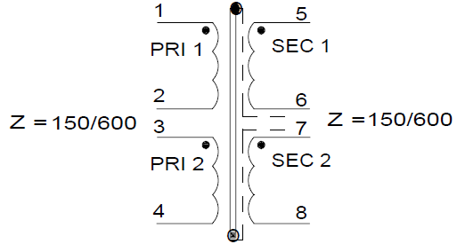
For the purpose of impedance matching and floating a single-ended, ground-referenced signal, I am planning to use an audio transformer like this one.
Here's the schematic from the data sheet:
![]()
My source has 150 Ω and I am using an output impedance of 600 Ω. Therefore, I am connecting pins 6 and 7 and feed the secondary (5-8) into my 600 Ω load. For the source, there appear to be several options:
- Feed the signal to 1-2 only, connect a 150 Ω resistor across 3-4. This will increase the power that has to be provided by the load, and the desired impedances cannot be achieved: 150 Ω source impedance matches 1-2, the additional 150 Ω resistor only appears to matches 3-4 but really messes up everything else, and the output resistor matches 5-(6,7)-8.
- Feed the signal to 1-2 only, leave 3-4 open. No additional power required for unused winding 3-4, impedances on 1-2 and 5-(6,7)-8 will match, but any parasitic capacitance across unused winding 3-4 might build a resonant circuit across this winding and degrade the fairly linear frequency response of the system. Might be a bad idea (?).
- Connect the two primaries in parallel. No additional resistor required, thus no additional power dissipation. Impedances on all windings will match: 150 Ω source impedance matches (1,3)-(2,4), and the output resistor matches 5-(6,7)-8. However, any possible mismatch between the two primary windings might degrade the performance. Mains (50/60 Hz) transformers that can be configured for either 115 V or 230 V are usually connected exactly this way to use the additional copper of the paralleled primary windings, but how about audio frequency transformers, where stray capacitance is a concern because (a) it is larger due to the high number of turns and (b) it matters more because we're using frequences up to 15 or 20 kHz instead of just 50/60 Hz?
Which option is preferred? Why?
Posts: 1
Participants: 1
Read full topic
↧
↧
December 28, 2017, 8:17 am
↧
December 28, 2017, 8:44 pm
@Lukff wrote:
I needed this part to create an illustration and made a new one as I couldn't find it available anywhere.
It isn't complete, though. I just needed the breadboard image, so it doesn't have the PCB footprint and the schematic is usable, but isn't good either.
I decided to publish it here because it may be useful for someone.
FC-03.fzpz (15.9 KB)
Posts: 1
Participants: 1
Read full topic
↧
December 28, 2017, 11:48 pm
@vanepp wrote:
The next in a series of chips that are useful for level translation between 3.3V and 5V (and the other way) systems. This one consists of 6 tristate output buffers in a 16 pin package. The enables are split so one controls 2 buffers and the other controls 4 buffers. Because the parts are in blocks, this part doesn't have subparts (although it can be converted quite easily if it is thought useful). As with the 74x125, various flavors of this will translate: the 74ahc367 running with VCC at 3.3V will accept 5V inputs and convert them to 3.3V. The 74ahct367 or 74hct367 with VCC at 5V will accept greater than 2.4V as a high level and will thus translate 3.3V outputs to 5V.
74x367.fzpz (10.8 KB)
Peter
Posts: 1
Participants: 1
Read full topic
↧