@Juanaca wrote:
Hello,im start in project electronic.i have the squematic but i dont know translater to fritzing.could somebody help me please¿
Posts: 6
Participants: 3
@Juanaca wrote:
Hello,im start in project electronic.i have the squematic but i dont know translater to fritzing.could somebody help me please¿
Posts: 6
Participants: 3
@vanepp wrote:
What do folks use to get an appropriate 2mm header pcb footprint? I I used the one generated by setting a standard header to 2mm pitch with inspector, but when I looked at the gerber the pads are way too large (almost no clearance between them). I found 2mm headers in the grove parts in core, but they use a path as the pad and that (as expected) doesn't export to the gerber. I'm going to manually adjust the header pads down to the 60 thou used in the grove parts and recalculate the hole size at .035, but is there a better footprint somewhere that I have missed? I can see there are several bug reports needed here
Peter
Posts: 6
Participants: 3
@zerox21 wrote:
I can't figure out why Fritzing is changing the circles on my pcb svg. In all other svgs the circle pads are correct.
SVG:
How can I make the PCB circles show up correctly?
Posts: 11
Participants: 3
@bvansambeek wrote:
Hello fellow Fritzing enthusiasts,
Thank you note
First love the fact that we can make our own PCB design in fritzing and order it for cheap on the internet.
I can make professional looking arduino projects, thanks to 2017, the internet and the community.Project
I try to make a pcb with two pads to be able to push a wire on the pcb that shorts a battery, LED and buzzer.
This will enable me to test wires, while working on other projects.
I therefore want two pads that are open to push a wire to it.Problem
In Fritzing I have two pads on the 'copper top' layer.
When I export to Gerber and upload to https://gerber-viewer.easyeda.com/ then I only see one pad on top.
I ordered it nevertheless and the pcb had only one open pad.
Here is the fritzing file
copper pad.fzz (4.1 KB)Can anyone help me to solve this issue?
Thanks in advance,
Boudewijn
Posts: 4
Participants: 3
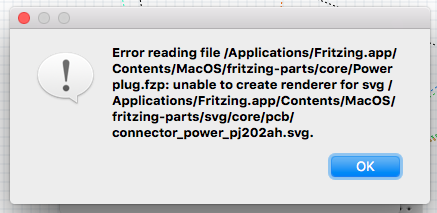
@jbund65 wrote:
Old Grey and Peter -
Thought I would try to edit the Power Plug in core parts. I must have done something wrong. The error messages I am getting are as follows:
My process was as follows:
Selected the power connector within the PCB layout.
Right click to Edit part.
In new part editor, selected part and went to show folder.
Opened in Inkscape.
Edited the XML code to change the "r" from 6000 to 2500.
Edited the XML code to change the stroke from 2000 to 1250.
Saved the file WITHOUT changing the filename. I thought this would be easier, because in the prior edits when I changed the part name, I could not find the new part, even though I was confident that the path and folders were accurate.I closed Inkscape.
I closed the parts editor.
Selected the parts from the core parts again ... and the error message occurred.Questions ... what did I do wrong.
How can I repopulate the core parts with the original file?
Why do I not see the "edited" version of the Inkscape file in the parts folder. Are separate files created for PCB and SCH and Breadboard ... even if I edit just the PCB?I have looked at the tutorials ... and except for the creation of a zip file and extraction, I think I have not violated any basic editing guidelines.
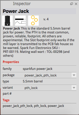
As an aside ... it appears there is a version of the power connector that has smaller pins but they are not exactly as the spec sheet for the part I am using. It is called "sparkfun-connectors_power_jack_slot_pcb.svg".
The following message is mentioned as a possible problem when using this power connector:
Would you please compare this or offer suggestions to which power connector image I should use to match the PJ-102AH power connector I am intending on using.
Here is the data specs for the PJ-102AH connector from Adafruit.
And here is yet another from Jameco Electronics:
This appears to match the larger holes that are the default "power connector" in the core parts bin. They are 3mm in diameter I believe.It seems the more I think I have this done ... the more details come up to bite me in the &&$%#!
Jim
Posts: 3
Participants: 2
@Milliways wrote:
I have Fritzing installed on my Mac 10.12.5 running Version 0.9.3 (b5c895d327c44a3114e5fcc9d8260daf0cbb52806 2016-04-19) Cocoa [Qt 5.6.0]
I use Fritzing infrequently and started on a new project.
I do not seem to be able to show the Parts Bin.
When I checked for Updates I got a warning and tried to regenerate the parts database.
This failed with error "Unable to open temporary file"Regenerating the parts database will take some minutes and you will have to restart Fritzing
Would you like to regenerate the parts database?
Unable to open temporary file
I reloaded Fritzing, which offered to update Parts, but failed in the same way.
Yet another reload which produced errors:-
Unable to find the following 13 parts:
'Taiway-100-SP-X-T1-X-X-B1-M1_SPDT_miniature_toggle_switch'
at
''I can run Fritzing, view my saved projects, and edit them, but cannot seem to get to Parts.
What can I do? I can live with losing all the existing parts.
Posts: 4
Participants: 3
@MHz000 wrote:
vorab: ich bin wohl auf dem neuesten Stand 0.9.3b.64.pc
mein erstes pcb layout ist bis auf die Masseverbindung fertig und der design check meckert auch nicht. Einzig und allein es ist das Netz GND nicht geroutet mit seinen 11 offenen Verbindungen. Was mache ich also um eine groundplane zu erstellen:
1. Routing
2 Massefüllung klicken und da fängt es schon an, denn zur Auswahl werden angeboten: Kupferfüllung oben und nochmal Kupferfüllun oben. Erwartet hätte ich auch Massefüllung oben/unten
ok Augen zu und weiter,
3. Saat für Massefüllung anklicken und es öffnet sich ein "erklärendes" popup Menü wo ich
4a ok anklicken kann aber nichts passier, wo ich auch
4b abbrechen anklicken kann und das popup Fenster wie erwartet verschwindet undwo ich ltztlich
4c "ok und Kupferfüllung" anklicken kann
wo dann was passiert - aber nicht das produziert wird, nämlich eine Kupferfüllung ohne Masseverbindung, was ich eigentlich wollte - sondern eine Kupferfüllung auf dem top layer erzeugt wird, leider ohne Masseverbindung. Das ist ja in sofern konsequent, als auch das nur unter 2 angeboten wurde :-((Wie gesagt das ist mein erster PCB-Entwurf also bitte nicht schimpfen oder lästern.Ich würde mich riesig über eine Schritt-für-Schritt und funktionierende Anleitung freuen.
Danke!
Und wenn ich was nachreichen kann auch hier die Bitte: genau sagen was und wie.
Posts: 2
Participants: 2
@vanepp wrote:
In this thread:
I have corrected the pcb layout for the Raspberry PI zero in core. That part is a no brainer as it is currently incorrect (not on .1 centers), but at the same time I found schematic to be correct but ugly in that it overlays power and ground pins, and is in a different order than the GPIO connector on the Zero (in fact the right hand pins are in the reverse order they appear on the connector as well as missing the power pins), so I created a new schematic that corrects the faults and adds pin numbers to the connections. The problem I see is if I submit this for addition to core (and do the right thing and do all the other PI models too, which I am willing to) it would break current sketches that used the current core parts. I expect this has come up before and there is an accepted solution, I just don't know what it is or how to do it so that sketches with the previous schematic still work. Can someone enlighten me on what I need to do to get this accepted?
Peter
Posts: 1
Participants: 1
@jbund65 wrote:
Peter, Old_Grey and others -
Thanks again for all the help with the two boards I have been working on. I think I am ready to order, and will be using Fritzing. The seamless process is worth the time in shipping. I have looked at the image files that they create for silk screen, drill holes and copper top and bottom traces. It seems that all holes are plated through ... as I would want.
Final thoughts about the additions I have made, and a question about using mini contactors.
For background, the boards are for remote monitoring of an Aquaponics project. The remote sensors will be attached to the "stereo" plugs and may have 20 feet or so of 26 ga. 3 conductor stranded wire to put them in place. I have also added a second power jack to monitor the "native" power in the building and look for a power outage. The main power jack for the electronics will be plugged into a UPS to maintain internet connectivity.
I chose to use two mini contactors (Omron G5V-1) ... one to sense the power failure by "releasing" a set of contacts which are normally held closed when power across the coil is present. I have added a resistor to the 5VDC power source because the coil amperage rating is 30ma and the "wall wart" power supply by default is 2000ma ... and I added a second resister to drop the 5 VDC to 3 VDC so I would not overpower the digital input pin (D8). Have not calculated the size resistor needed
, but I think using Ohms law, I can figure that out (hopefully).The second mini contactor is used to sound a buzzer ... again when some condition exists that would need notification. I have used D5 as the pin which I will set "high" to act as the trigger to energize the coil which powers the buzzer. I feel I can use this to sound the buzzer when any "digital read" condition is out of bounds. I felt that I should add a "pull down" resister to that pin (or perhaps in the code I could set that option).
I do not have a lot of experience with the need for diodes or capacitors and thank you all for you help and patience.
Attached are the Fritzing files as they exist now.
Jim
Aquaponics main board 6_26_17.fzz (66.7 KB)
MRK1000 6_26_17 LCD board w_cap and buzzer.fzz (15.1 KB)
Posts: 2
Participants: 2
@jonathanmallinson wrote:
Hi Everyone, Jonathan here, I am looking for an Electronics Designer for a short project that I am willing to pay for for a few days, maybe weeks depending on how good their work is. Please E-Mail me for more information . Thanks Jonathan - E-Mail: info@asianreplicas.com
Posts: 1
Participants: 1
@impellbm wrote:
I need a round layered pcb made. Id like someone with excellent electronics knowledge to reply with an email. It is very simple, I think maybe, ten connections from a drv8833 to a feather rfm95. Hard part for me at least comes in simplying everything which is not needed out. Thanks! I prefer an individual, broke electronics engineering student or the like who needs the money rather than a company.
Posts: 1
Participants: 1
@fieryfire wrote:
Hi Guys,
I have a serious problem. I had designed an entire PCB around a QFN-24 pin (3.5mm x 3.5mm) layout on fritzing. But only on ordering the PCB i came to realize that the fritzing supports only 4mmx4mm and not the 3.5mm x 3.5mm kind. I am facing serious trouble here since, a small mistep is causing a huge problem when it comes to soldering the chip. Is there a way to create the 3.5mm x 3.5mm version in fritzing . I tried looking at all available parts but it does not seem to exist. Could someone help me to find it? or how to modify it?
Posts: 3
Participants: 3
@basestring wrote:
Hi foks,
I've been looking everywhere for a db15 vga connector part.
at the end i've been puzzling to make it my self.
so at the end after a 1.000.000 tries I got it. both male and female.I don't really care about breadboard view so I just made 15 pins
1 to 15 from left to rightThis is female type I made
CheersHere are the Part files
DB15 VGA FEMALE.fzpz (8.8 KB)
DB15 VGA MALE.fzpz (9.0 KB)Cheers
Posts: 1
Participants: 1
@Pako wrote:
I created the .fzpz file for another (other than the RDM6300) 125 kHz RFID module.
RF125-PS.fzpz (14.1 KB)
I also wanted to add original .SVG files, but it is not possible.
ZIP is not authorized and SVG from Inkscape returns this message:![]()
Posts: 2
Participants: 2
@Way wrote:
I made ADC1015 & ADS1115 parts for Fritzing. There is a one issue- schematic view have problem with font. Although I had install Droid Sans, in Inscape everything is OK, but in Fritzing no. If You know how to fix it, please let me know. <a class="attachment"
ADS1015.fzpz (12.2 KB)
ADS1115.fzpz (12.0 KB)
Posts: 3
Participants: 3
@basestring wrote:
I created the ITDB02 TFT Arduino Mega Shield
v2.0Use this part if you want to mount it on pcb instead of your arduino.
I also edit the arduino mega with a mirrored pcb layout, this way you can mount your arduino on your pcb instead the other way around
ITDB02 TFT MEGA SHIELD.fzpz (28.0 KB)
Posts: 1
Participants: 1
@dante111 wrote:
Can I get a picture of IBT-2 Motor Driver 43A H-Bridge Drive
Posts: 4
Participants: 2
@juliusbangert wrote:
I am having a problem where Fritzing just crashes and hangs when I choose to do a gerber export. When I look in the export folder it has only got as far as the pnp.txt file.
Does anyone have any idea what might be happening? It seems to be a problem with my file because I've tried this Fritzing project file and it exports fine.
I don't understand what is wrong with my particular file to cause these crashes.
( I have saved the osx crash report after force quit if this helps the developers at all. )
Posts: 3
Participants: 3
@nsollars wrote:
Hey everyone,
So I went walking around google for anyone whom may have made or perhaps started to make a part for this new part, unfortunately I came up with nothings so I thought id reachout as I have 2 of these boards and would very much like a part made for them.
I am no expert at fritzing ( am looking at tutorials though ), so just looking for a little help or perhaps help someone else with the same idea..
Nige
Posts: 1
Participants: 1
@chiefartificer wrote:
This is my first time using a PCB Design tool. I created a PCB design for a super simple RCA connector module. My intention is to create something similar to the attached image. I have attached my .fzz file and would appreciate any suggestion or correction.
Thanks in advance!
RCA.fzz (3.2 KB)
Posts: 3
Participants: 2